
User's Manual

Preliminary
AMS-9060 CONTROLLER 8200-1014-01, REV. 1A
INSTALLATION GUIDE
4 of 13
Implanted Medical Devices
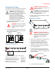
This anti-theft system complies with all applicable
safety standards. However, people with implanted
electronic medical devices may ask if the store has
an anti-theft system and its location. Although most
anti-theft systems are easily seen, some can be
concealed. To help these people, do the following:
Consider Health and Safety
Place the anti-theft system antennas so customers:
do not linger near or lean on them while making
their purchase
are only near the front of them while exiting the
checkout area.
For exit systems, place anti-theft system antennas:
Close to exit/entrance doors, encouraging the
customer to pass through them. DO NOT use
antennas intended for exits in an aisle
configuration.
Away from fixtures, equipment, amusements,
and other signage that can attract customers to
them.
Apply “Anti-Theft” Signage
“Anti-Theft” labels are placed on each antenna,
including those hidden behind door frames and
other structures. DO NOT cover these labels
with other signage.
In non-English speaking countries, apply “Anti-
Theft” labels in the local language to the
antennas. For hidden antennas, apply an “Anti-
Theft” label in the local language to each side of
the door frame facing the doorway about 1.2m
(4ft) above the floor. Order local language
labels (2412-0170-XX) from your distribution
center.
To improve customer awareness of the anti-
theft system, encourage the store to display
signs that state it has an anti-theft system.
Order awareness materials through your sales
representative.
Controller Installation
Tools required:
Tape measure
Pencil or marker
Electric drill
Phillips-head screwdriver or bit
Hand vacuum or broom
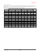
Parts required:
Install Kit 0352-0286-02
Part
Qty.
Part number
Clamp, conduit
10
6010-0107-01
Label, Denan
0352-0398-07
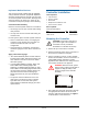
Mounting the Controller
CAUTION: Keep 22.9cm (9in) of free
space to the right of the controller for
screwdriver access (to facilitate
detachment of controller electronics).
1. Detach the top cover from the controller.
2. Remove knockouts closest to the connectors to
be used, then reattach the side plate.
3. Set the controller on a shelf, or using suitable
anchors and hardware, mount it to a wall or to a
ceiling. Note: Ceiling attachment requires
plywood be first attached to the ceiling and then
the controller attached to the plywood.
WARNING! Both the anchor system
and the wall or ceiling must be able to
support 12.08kg (26.6 lbs) or four
times the weight of the controller
assembly.
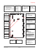
4. Run cables from antennas and devices through
the appropriate knockouts and secure them
using the cable clamps provided. See Figure 1
for the locations of the connectors.