
User's Manual

Preliminary
AMS-9060 CONTROLLER 8200-1014-01, REV. 1A
INSTALLATION GUIDE
6 of 13
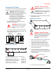
6. Remove one of the knockouts accessing the
ac connection area. Thread a cable clamp into
the hole.
7. Route the ac cable through a cable clamp,
leaving about 15.2cm (6in) out the other side.
Tighten the clamp around the cable.
8. Put the ferrite on the Line (L1), Neutral (L2)
and ground wires. Ensure the wires wrap
around the ferrite and pass through again like
they did on the existing wiring harness.
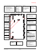
9. Expose about 5cm (2in) of insulated wires:
Line (L1), Neutral (L2), and ground.
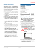
10. Connect the AC power wires to the power
connector P1 on the main board in the
pedestal.
The power connector accepts 0.75 to 2.0 mm
2
(18 to 14 AWG) wire. Connect the Line wire
(black) to pin 1, the Neutral wire (white) to pin
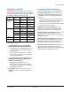
2, and the ground wire (green) to the screw on
the main board, as shown below.
If you remove the connector, do not pull it out
by the wires; pull on the connector.
When connecting the ground wire, ensure the
slot on the washer is pointing down to allow the
jacket on the cable to fit behind the washer.
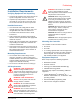
CAUTION: After you connect the
ground wire, ensure all of the strands
of the ground wire are beneath the
washer. Loose strands can cause a
short circuit.
Connecting Pedestals
Transceiver pedestals connect to the AMS-9060
controller with two cables: Transceiver (Tx/RX)
cables and Alarm/Communication cables. They
connect to the controller at the following
connectors:
Transceiver connectors (P19, P21, P23,
P25). These four connectors labeled PED A, B,
C, and D, support Tx/Rx antennas designated
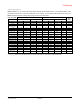
A, B, C, and D. Table 1 shows connections for
various antenna configurations. If “auto
configuration” is enabled, the system
automatically attempts to configure itself based
on the number of antennas detected. Only the
most commonly used configurations are auto
configured.
Alarm/Communication connectors (P20,
P22, P24, P26): Four connectors support the
antennas audio/visual alarms, transmitter/
alarms inhibit function, and peripheral RS-485
network communication. Note:
Transmitter/Alarms inhibit function and
peripheral RS-485 network communications
are only available in Ultra•Exit alarm antennas
and Pro-Max 5 pedestals.
WARNING—RISK OF ELECTRIC
SHOCK! The ac power cord may carry
120Vac or 240Vac.
1. Ensure controller power is off.
2. Connect antenna cables to the controller
according to how the antennas are intended to
perform. Refer to diagrams and tables on pages
8 and 9 of this guide. See examples of pedestal
installations in the antenna installation guide.
Ground screw
Washer (slot
points down
towards wire
jacket)
Ground wire
Cable
jacket