
User's Manual

Preliminary
AMS-9060 CONTROLLER 8200-1014-01, REV. 1A
INSTALLATION GUIDE
7 of 13
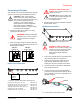
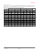
Connecting Receivers
Auxiliary receivers connect to the AMS-9060
controller at the following connectors, with top coils
connecting to the Coil 1 connections and bottom
coils using the Coil 2 connections:
Receiver 1 (P3)
Receiver 2 (P4)
Receiver 3 (P5)
Receiver 4 (P17)
Antennas/coils connected to receiver inputs are
designated A, B, C, and D. These connectors
default to receive function with no auto detection.
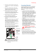
ABOUT NOISE CANCELING COILS:
Noise canceling coils, such as a Ranger antenna
or the top coil of a pedestal antenna, are used to
cancel noise that interferes with detector operation.
Noise canceling coils only connect to the top
coil (Coil 1) input on connectors P5 and P17.
To accept a noise canceling coil, the auxiliary
input must be in noise canceling mode (set
using service configurator software). Save
adjustments to default settings if they are to be
used on the next power cycle or system reset.
Move the noise canceling coil around while
monitoring power levels on a laptop computer to
find where noise cancellation is best. This is
where the coil should be installed.
The location for the noise canceling coil must be
practical as well as yield satisfactory results.
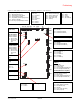
If connecting a noise canceling coil and a
receive antenna into the same connector, the
top and bottom coils of the receive antenna
must share the Coil 2 connection (done in the
field by the technician switching the antenna
wire connections). Thus phase flipping is
unavailable when noise canceling coils are
used.