
User's Manual


BIS-4170 IVS PEOPLE COUNTER 8200-2702-01, REV. 4A
INSTALLATION AND PLANNING GUIDE
10 of 23
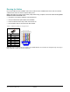
To a Ceiling Tile
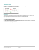
1. Do the following to prepare the tile (Figure ):
• Remove the ceiling tile and drill a ¼-inch hole in its center.
• Cut a 2.5ft piece of wood 2x4 and drill a ¼-inch hole in its center.
• Center the 2x4 above the tile structure. Then place the ¼-20 threaded rod though the hole and secure it
from above and below with two ¼-20 nuts. Ensure the rod extends only about ¼-inch below the tile.
• Reinsert the ceiling tile with the threaded rod protruding through the hole in the tile.
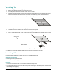
2. Do the following to attach the IVS device (Figure ):
• Loosen the two bottom screws in the IVS device and remove its top shell.
• Thread the top shell to the threaded rod until it is secure against the tile.
• From the underside of the tile, punch a cable access hole in the tile above the opening(s) in the top shell.
3. Run the video cable from the DVR, above the tile ceiling, and through the opening in the top shell.
4. Push the end of the Cat5 and pigtail cables down through the openings in the top shell.
To a Ceiling T-Bar
Mounting brackets enable the IVS device to mount to a suspended ceiling T-bar.
Additional Parts Required
• Mounting Brackets (2): 0500-7193-01
• Screws, Pan head, M3x8 (2): 5801-1051-120
Procedure
1. Loosen the two bottom screws in the IVS device and remove its top shell.
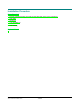
2. Cut a triangular piece off of the rubber flap to keep it from interfering with the locking screw. Repeat for the
other locking screw (Figure ).
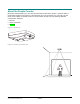
Traffic Direction
Cable Access
IVS Device