
User Manual


2 SETUP AND SERVICE GUIDE
DIGITAL MICROWAVE SYSTEM 915
8000-0395-02, REV. B
About the DMS 915
The Digital MicroWave System (DMS) 915 is a
microcontroller-based anti-theft system. The DMS
915 produces an alarm when it detects a
Sensormatic tag, a packaged semiconductor
diode.
To detect the tag, the system performs the
following operations:
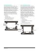
• The system generates a “zone of protection,”
typically at a store exit. This zone consists of
two overlapping fields. The first field is a static
or frequency-hopping, frequency modulated
RF signal. The second field is a frequency shift
key (FSK) modulated and predominately
electrostatic field called an E-field.
• When a tag enters the zone, it combines the
RF signal and the E-field into a composite
signal that radiates to the system RF
antennas. The system detects the composite
signal, separates the modulation, and
compares the recovered modulation to the
modulation transmitted. If the two signals
match, the system issues an alarm.
The DMS 915 is programmed using an external
hand-held computer. Programmable features
include RF hopping bank or frequency selection,
RF power level selection, electrostatic field
frequency selection, “tag-too-close” function
enable/disable, alarm tone selection, alarm
duration selection, selectable hits required for
alarm, and alarm count set/reset control.
System Components
DMS 915 components include E-field radiators, RF
antennas, remote alarms, and a programmable
power pack
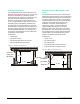
Three types of E-field radiators are:
• Wire cloth – usually recessed in the floor or
sometimes laid on the floor under a rubber
pad.
• Plate – a metal plate concealed inside a
pedestal at the side of the exit.
• Vortex – a long aluminum bar hung across the
exit.
The RF antennas are used to radiate the
frequency-hopping, frequency-modulated RF
signal. These antennas mount in a variety of ways.
They can be concealed above the ceiling,
mounted in pods, concealed in the floor, or
mounted in pedestal enclosures located at the
store exit.
The remote alarm provides a audio/visual signal
that a tag has entered the “zone of protection.”
The power pack powers and controls the system.
The pack is typically concealed inside an
enclosure.
Board Replacement
The new RF Transmitter/Receiver Board (0300-
2469-01) is not compatible with the old
Processor Board (0300-0928-01). If the old RF
Transmitter/Receiver Board (0300-0385-01) is
replaced with a new RF Transmitter/Receiver
board, the old Processor Board also must be
replaced with Processor Board 0300-0928-02.
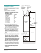
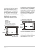
Antenna Connection
Change
Connect the Impedance Matching Filter (SEC
p/n 0400-1379-01) to the outer RF port (farthest
from the IF module). Refer to Figure 1.
Connect one of the RF antennas to the filter.
Connect the other RF antenna directly to the
remaining RF port.