
User's Manual
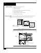
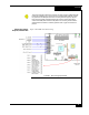
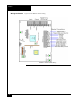
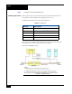
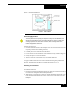
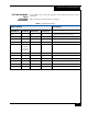
Table Of Contents

Installation
5
Grounding and
Shielding
When bus wiring more than one RM-iC reader (Figure 5 ):
1. Attach the shields along the bus together (insulate each connection). Snip off the
shield wire at the end of the bus.
2. Attach the shield to the ground at only one point, the ground stud inside the cabinet
adjacent to the knockout.
3. Attach a local earth ground (18 or 22 gauge) wire to the J5 component.
FIGURE 5. Reader Shield Wiring
Setting Module
Address and
EOL Termination
To set the module address, set SW1 (16 position rotary switch) to a number from one to
eight. Every RM-iC series reader on a bus must have a unique address.
To set RS-485 EOL termination, set SW3-5 to the On (closed) position if the module is
the last unit in the bus. If the module is not last, SW3-5 should be Off (open).
Installing the ARM-1
Relay
Two ARM-1 relay components can be connected to the RM-iC series reader through the
P5 connector (Table 1 ).
P5-1 is the common (+12 VDC) pin for either ARM-1.
P5-2 is the output drive (GND) for the first relay.
P5-3 is the output drive (GND) for the second relay.
ACM module
RS-485 connector on a reader
Knockout
Twist shield wires together and insulate
(do not ground)
Ground stud
(bus configuration)
Shield wire
Enclosure/cabinet
Shield wire
Snip off shield
wire at end of
bus
TABLE 1. ARM-1 Wiring
Module Wiring
ARM-1 Relay P2-1 to RM P5-1, P2-2 to RM P5-2
ARM-2 Relay P2-1 to RM P5-1, P2-2 to RM P5-3