
User's Manual
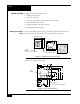
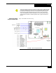
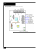
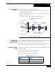
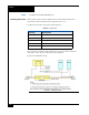
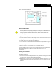
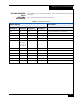
Table Of Contents

Testing with apC or iSTAR hardware
8
3. Use two (Quantity 2) 6-32 x 1/4" screws to mount the thermostat to the RM Plate.
Tighten the screws allowing the thermostat to be sufficiently secured to the plate. Do
not over tighten the screws.
TESTING WITH APC
OR ISTAR
HARDWARE
To test an RM-iC series reader with an apC or iSTAR:
1. Measure the supply voltage to the RM-4.
The voltage can be measured between pin 1 (+12 VDC supply) and pin 4 (ground)
on the P4 connector. The voltage must be +12 VDC (+/-5%).
2. Check the RM-iC reader address setting.
The RM-iC must be set to an unused address, between 1 and 8, when connected to
the apC or iSTAR. Use rotary switch SW1 to set the reader address.
3. Check the RM-4 for communications to the apC or iSTAR. Observe LED2 and
LED3.
4. Check the supervised inputs. Configure the inputs on the apC or iSTAR.
With no switches or resistors connected to the supervised input 1 and 2 lines, the C•
CURE 800/8000 Monitoring Program should report inputs as “Open Loop”. When
you connect the 1,000-ohm resistor to the input terminals, the C• CURE 800/8000
Monitoring Program should report that the input as “Deactivated”. Supervised
inputs #1 is found at pins 4 and 5 of P5. Supervised input #2 is found at pins 6 and 7
of P5.
5. Check the outputs.
The outputs can be functionally tested by using the “momentary activate” feature in
the C• CURE 800/8000 Monitoring Program. When the outputs are momentarily
activated, the signal will change state for a few seconds. A 1,000 ohm resistor and an
LED can be connected to the output to obverse the functionality. Connect the
resistor to pin 1 of P5 (+12VDC). Connect the anode of the LED to the resistor and
connect the cathode to pin 2 of P5 for output #1 and to pin 3 of P5 for output #2.
6. Check the reader interface.
The reader interface can only be tested with the reader chosen for the installation.
Reading a card will cause the display to show “Access Granted” or “Access
Denied”, depending upon the clearance of the card.