
Smoke Alarm User Manual


5-17
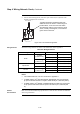
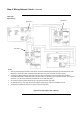
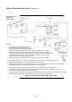
The figures below show how to wire the NIC. The illustrations use the 565-274 and 565-
275 motherboards only. If you are using the 4100U motherboard, refer to Figure 5-11
along with the figures below.
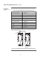
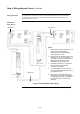
Figure 5-12. Wired Media, Style 7 Wiring
Continued on next page
Step 4. Wiring Network Cards, Continued
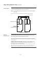
Wiring Illustrations
Wired Media,
Style 7 Wiring
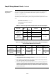
Notes:
1. Refer to general wiring precautions in this
chapter, as well as Field Wiring
Specifications: document 900-082 for
4100; 900-242 for 4100U.
2. When the 565-413 Interface Card is used
with 565-516, -407, or –409 Network
Card, TB1 on the 565-413 Interface Card
cannot be used. Connection to the
motherboard is required as shown.
3. The shield should only be connected at
one end of the line. The shield is
connected to the left port.
4. On assembly 565-274, JW1 and JW2
must be installed. Jumper plugs must not
be installed on P5-P8.
5. Each “wired” media cable requires two
ferrite beads, one at each end (included in
the shipping group). Refer to installation
instructions 574-041 for proper bead
mounting.
SEE NOTE 3
SEE NOTE 5
SEE NOTE 3