SPECIALTY PRODUCTS Installation & Service Manual NSSD THREE DECK MEAT/DELI/CRITICAL TEMP PRODUCE MERCHANDISERS WITH CURVED FRONT GLASS Medium Temperature Self Serve Display Cases This manual has been designed to be used in conjunction with the General (UL/NSF) Installation & Service Manual. Save the Instructions in Both Manuals for Future Reference!! This merchandiser conforms to the American National Standard Institute & NSF International Health and Sanitation standard ANSI/NSF 7 - 1999.
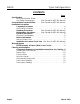
NSSD Tyler Refrigeration CONTENTS Page Specifications NSSD Specification Sheets . . . . . . . . . . . . . . . . . . . . . . . . . . . . . . 4 Line Sizing Requirements . . . . . . (See General-UL/NSF I&S Manual) Pre-Installation Responsibilities . . . . . (See General-UL/NSF I&S Manual) Installation Procedures Carpentry Procedures . . . . . . . . . . . . . . . . . . . . . . . . . . . . . . . . . 6 Case Pull-Up Locations . . . . . . . . . . . . . . . . . . . . . . . . . . . . . . . . .
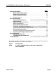
Installation & Service Manual NSSD Page General Information NSF Product Thermometer . . . . . . . . . . . . . . . . . . . . . . . . . . . . 13 Radiant Heat Information . . . . . . . . . . . . . . . . . . . . . . . . . . . . . 13 Radiant Heat Measurement . . . . . . . . . . . . . . . . . . . . . . . . . . . . . 14 Display Practices . . . . . . . . . . . . . . . . . . . . . . . . . . . . . . . . . . . . . 14 Service Instructions Preventive Maintenance . . . . . .
NSSD Tyler Refrigeration SPECIFICATIONS NSSD Three Deck Meat/Deli/Critical Temp Produce Merchandisers Page 4 October, 2002
Installation & Service Manual NSSD NSSD Three Deck Meat/Deli/Critical Temp Produce Merchandisers October, 2002 Page 5
NSSD Tyler Refrigeration INSTALLATION PROCEDURES Carpentry Procedures Case Line-Up NOTE The NSSD cases are shipped on casters that are replaced with adjustable legs during case line-up and installation. See the “General-UL/NSF I&S Manual” for the proper case line-up procedures. Case Pull-Up Locations Electrical Procedures Electrical Considerations CAUTION Make sure all electrical connections at components and terminal blocks are tight.
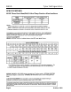
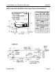
Installation & Service Manual Defrost Information CAUTION See “General-UL/NSF I&S Manual” for operational descriptions for each type of defrost control. Defrost Control Chart Defrost Defrost Defrosts Duration Per Day (Min) Type Off Time 6 28 Electric 6 36 Gas 6 12-15 NSSD Term. Temp. ---50°F 55°F E = Electric Defrost Termination G = Gas Defrost (Fan Delay) F/S = Electric Defrost Failsafe (Opt.
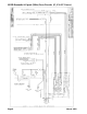
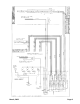
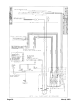
NSSD Domestic & Export (50Hz) Case Circuits (6’, 8’ & 12’ Cases) Page 8 March, 2002
March, 2002 Page 9
Page 10 March, 2002
March, 2002 Page 11
NSSD CLEANING AND SANITATION Component Removal and Installation Instructions for Cleaning Shelves and Shelf Brackets 1. Remove product from shelves. 2. If shelf has a light, unplug the light cord from the socket in the rear duct panel. Completely insert socket cover in the light socket to protect the receptacle. 3. Push shelves back and then lift up and out to remove them from the shelf brackets. 4. Remove shelf brackets from slots in rear uprights. 5. After cleaning, replace in reverse order.
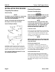
Installation & Service Manual Front Upper Cladding NSSD Radiant Heat Information 1. Remove plexiglas from plexiglas retainer. Remove screws and plexiglas retainer from top of bumper retainer 1. Remove color band, bumper and bumper retainer from the case. (See GeneralUL/NSF I&S Manual.) 2. Remove front kickplate. 3. Remove screws and front lower cladding. See page 12. 4. Remove screws from top and bottom of upper cladding and remove front upper cladding. 5.
NSSD Tyler Refrigeration temperatures rise above 45°F. This prematurely discolors displayed meats and causes unnecessary meat department losses. Ballast and Lighting Locations Radiant Heat Measurement Place two accurate dial thermometers side by side in a case. Cover one of the thermometer stems with black friction tape. The temperature difference is the approximate amount of radiant heat.
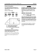
Installation & Service Manual NSSD Rear Ballast Location Replacement 1. Remove screws (1) and rear rail cover (2) from rear of case. NOTE If tappit screws are not available, a starwasher should be used between the ballast and the heads of the screws. 1. Remove bottom trays (1) from case (2). 2. Install required number of ballasts (3) in rear electrical raceway (4) with two screws (5) each. 3. Identify and connect required wiring harnesses (upper, lower, etc...) to the ballast connectors (6). 4.
NSSD Tyler Refrigeration Anti-Sweat Replacement WARNING Front Curved Plexiglas Replacement Shut off or disconnect power supply to case before changing an anti-sweat. Electrical power from wire ends could damage other components and/or cause personal injury or death. Top Light Channel Anti-Sweat Replacement 1. Remove two screw (1) and plexiglas joint trim (2) from both joints of the damaged plexiglas (3). 2. Remove damaged plexiglas (3) from plexiglas retainer (4). 3.
Installation & Service Manual NSSD PARTS INFORMATION Operational Parts List Case Usage Domestic Electrical Circuit 115 Volt 60 Hertz Case Size 6’ 8’ 12’ Fan Motor 5243498 9 Watt 5243498 9 Watt 5243498 9 Watt Fan Motor Brackets 5962268 5962268 5962268 Fan Bracket Plate 9041077 9041077 9041077 Fan Blades (7” 35° 5B) 9044934 9044934 9044934 Opt. ECM Fan Motor 9025002 8 Watt 9025002 8 Watt 9025002 8 Watt Opt. ECM Fan Motor Brackets 9025005 9025005 9025005 Opt.
NSSD Tyler Refrigeration Cladding and Trim Parts Lists NSSD Item Description 6’ 8’ 12’ 5100217 (2) 5100217 (2) 5100217 (2) 1 Screw (per cover) 2 Joint Trim, Rear Riser 5932659 5932659 5932659 3 Plexiglas, Curved 9800193 9800194 9800193 (2) RH Plexiglas Trim Assy. 9800225 9800225 9800225 LH Plexiglas Trim Assy.
Installation & Service Manual NSSD March, 2002 Page 19