
Users Manual


Operational description
RF-module
This document is the sole property of Tyro Products B.V.
Any reproduction in part or as a whole without the written permission of Tyro Products B.V. and/or the author is prohibited.
Page 6 of 9
With the chosen topology there is a central master in each set that communicates with multiple slaves.
The slaves do not communicate with each other.
The master ensures that all modules within a system are synchronized and use the same cycle timing.
In a cycle there are several time slots for the master itself and for the different slaves.
Time slots are always reserved for the maximum number of slaves (10), even though not many slaves are used.
A master and a slave are hardware and software moderately the same, only configured differently at runtime.
The rest of this document is based on the above topology.
3.4 Communication interface
- SPI interface (standard)
- I2C interface is defined in hardware (option for future firmware versions)
- IRQ line (packet received in RX mode, packet send in TX mode)
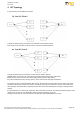
3.5 SPI interface
- Details of the SPI-interface are defined in the SPI-interface-document.
3.6 Payload and addressing
The combination of the chosen cycle time, baud rate and payload size means that it is not possible
for all slaves to send the maximum format message (24 bytes) in the same cycle.
Therefore, in this topology it is decided that each slave in each cycle can send a “status message” with a fixed size
of 5 bytes. A single slave designated by the master as an “active slave” sends a complete message in a specially
designated time slot instead of a status message.
It is also possible that the master does not designate an active slave, so that all slaves send a status message.
The master can indicate in the header of a message for whom that message is intended. It can be for a single
specific slave or for all slaves. The slave is set by default to respect this addressing and only put data in the RX
buffer that is intended for it. It is possible to place all messages that his master sends in the RX buffer.
This functionality is necessary to maintain a safety-tested out-of-range security without forcing the master to always
send everything as broadcast.
3.7 Response speed
The response speed of our systems is specified at 100ms.
This is counted from pressing the button on the transmitter to switching the relays on the receiver.
Reading the keyboard, sending to the module, reading from the module, transferring over the internal bus and
switching the relay takes worst-case 35ms together. This would leave 65ms for the radio itself.
This response speed only applies from the sender to the receiver and in many of those situations
the full 24 bytes payload is not required
3.8 Buffer
- The master has a separate receive buffer for each slave that can contain 1 complete message.
- The slave has a single buffer that can contain 1 complete message.
- Both have a single transmission buffer that can contain 1 complete message.
3.9 Pairing
All receivers have a button that allows the user to put the receiver in pairing mode. Such a button is not present on
the channels. Therefore, it will be necessary for a transmitter to be able to attempt to initiate a pairing process
without disrupting normal operation if there is no receiver nearby that is also in pairing mode.
The SPI interface document describes a pairing method that meets this requirement.