
User's Manual
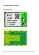
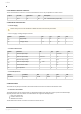
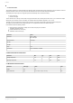
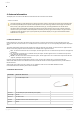
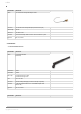
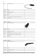
Table Of Contents

u-blox
Copyright © 2014 u-blox AG Page 6 of 24
3.3 J6 External Antenna Connector
J6 is the external antenna connector. It is used for both transmit and receive. The port impedance to match is 50 ohm.
J6 pin nr Pin name Signal level Type Description
1 Ant-1 RF I/O U.FL. external antenna port (50 ohm)
3.4 Electrical Characteristics
3.4.1 Power Supply
3.4.1.1 Supply Voltage Requirements
Symbol Parameter Min Typ. Max Unit
V
DD
Supply voltage 3.0 3.3 3.6 V
V
IO
IO Supply voltage 1.75 1.8 1.9 V
3.4.2 I/O DC Characteristics
Symbol Parameter Min Typ Max Unit
V
IL
LOW level input voltage 0 0.35 x V
IO
V
V
IH
HIGH level input voltage 0.65 x VIO V
IO
V
V
OL
LOW level output voltage 0.0 0.45 V
V
OH
HIGH level output voltage V - 0.45
IO
V
IO
V
I
IO
Sink and source current 8.0 mA
C
IO
Input capacitance 8 pF
3.4.3 LPO Requirements
Symbol Parameter Min Typ Max Unit
LPO-32kHz Frequency 32763 32768 32773 Hz
3.5 Host Interface
The module has two primary host interfaces, SDIO for the Wireless LAN section and UART for the Bluetooth section.
3.5.1 Wireless LAN and SDIO
The interface between the host and the module is a standard SDIO interface (See SDIO spec Version 2.0) with Out Of Band interrupt,
supporting maximum clock rate of 25MHz. The SDIO interface also supports the following features:
Both 1 and 4 bit data bus
Functions number 0 and 2
Multi-Block data transfer
The WLAN block uses function 2. Function 0 is used for the common I/O area.
Read the safety notes in section Guidelines for Efficient and Safe Use before using the modules.