User's Manual
Manuals
Brands
u-blox Malmo Manuals
Electronics
WLAN & Bluetooth Module
1
2
3
4
5
6
7
8
9
10
Table Of Contents
Introduction
Document Overview
Key Features
Product Variants
Electrical Interface and Connectors
Primary Side Connector
Secondary Side Connector
J4-20 RF-port solder land
Electrical Characteristics
Power Supply
Supply Voltage Requirements
I/O DC Characteristics
LPO Requirements
Host Interface
Wireless LAN and SDIO
Bluetooth UART
Environmental Characteristics
Mechanical Characteristics
Antenna Information
Caution
External Antennas
Antennas
Mounting Information
Module Dimensions
PCB Solder Lands
Host Board
Mounting Process
Regulatory Information
CE compliance
Equipment classes
Declaration of Conformity
IC and FCC compliance
IC compliance
Conformité aux normes d’IC
FCC statement
End product labelling requirements
FCC end product labelling
IC end product labelling
Étiquetage du produit final conforme à IC
Antenna
Caution
Ad-hoc frequencies
RF-exposure statement
Compliance with RoHS Directive
Guidelines for Efficient and Safe Use
General
Product Care
Radio Frequency Exposure
Electronic Equipment
Potentially Explosive Atmospheres
Safety Compliance
-
-
Page
of
6
21
2 Electrical Interface and Connectors
Host interface and control signals are accessible via PCB solder lands at the edge of the PCB.
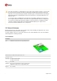
2.1 Primary Side Connector
Top view of module, J4 is the 2 x 18 pin solder lands.
1
...
...
4
5
6
7
8
...
...
21