
User's Manual


TOBY-R2 series - System Integration Manual
UBX-16010572 - R04 System description
Page 10 of 147
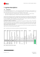
1.2 Architecture
Figure 1 summarizes the internal architecture of TOBY-R2 series modules.
Cellular
Base-band
Processor
Memory
Power Management Unit
26 MHz
32.768 kHz
ANT1
RF
Transceiver
ANT2
V_INT (I/O)
V_BCKP (RTC)
VCC (Supply)
SIM
USB
GPIO
Power On
External Reset
PAs
LNAs Filters
Filters
Duplexer
Filters
PAs
LNAs Filters
Filters
Duplexer
Filters
LNAs FiltersFilters
LNAs FiltersFilters
Switch
Switch
DDC(I
2
C)
SDIO
UART
Digital audio (I
2
S)
ANT_DET
Host Select
Figure 1: TOBY-R2 series modules simplified block diagram
TOBY-R2 series modules internally consists of the RF, Baseband and Power Management sections here described
with more details than the simplified block diagrams of Figure 1.
RF section
The RF section is composed of RF transceiver, PAs, LNAs, crystal oscillator, filters, duplexers and RF switches.
Tx signal is pre-amplified by RF transceiver, then output to the primary antenna input/output port (ANT1) of the
module via power amplifier (PA), SAW band pass filters band, specific duplexer and antenna switch.
Dual receiving paths are implemented according to LTE Receiver Diversity radio technology supported by the
modules as LTE category 1 User Equipments: incoming signal is received through the primary (ANT1) and the
secondary (ANT2) antenna input ports which are connected to the RF transceiver via specific antenna switch,
diplexer, duplexer, LNA, SAW band pass filters.
RF transceiver performs modulation, up-conversion of the baseband I/Q signals for Tx, down-conversion and
demodulation of the dual RF signals for Rx. The RF transceiver contains:
Single chain high linearity receivers with integrated LNAs for multi band multi mode operation,
Highly linear RF demodulator / modulator capable GMSK, 8-PSK, QPSK, 16-QAM,
RF synthesizer,
VCO.
Power Amplifiers (PA) amplify the Tx signal modulated by the RF transceiver
RF switches connect primary (ANT1) and secondary (ANT2) antenna ports to the suitable Tx / Rx path
SAW duplexers and band pass filters separate the Tx and Rx signal paths and provide RF filtering
26 MHz voltage-controlled temperature-controlled crystal oscillator generates the clock reference in
active-mode or connected-mode.