
Integration Manual


JODY-W3 series - System integration manual
UBX-19011209 - R07 System description Page 7 of 71
C2-Restricted
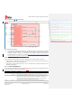
Figure 1: JODY-W354 and JODY-W374 block diagram
Figure 2 shows the block diagram for the JODY-W377 module variant.
Figure 2: JODY-377 block diagram
☞ JODY-W3 series modules with dedicated LTE coexistence filters (2.4 GHz BPF) are available
on request. Coexistence filters are recommended for designs with co-located LTE devices
operating in bands 7, 38, 40, or 41. Depending on the design, standard JODY-W3 series
modules include ceramic diplexer or LPF filters. Information about which module versions that
includes dedicated LTE filter is available in [1].
1.1.2 Radio interfaces
JODY-W3 series modules support Wi-Fi 6 802.11a/b/g/n/ac/ax and Bluetooth 5.3 operations:
• JODY-W354 and JODY-W374 provide two antenna ports, one for dual band Wi-Fi (2.4 GHz and
5 GHz) and one for 5 GHz Wi-Fi and Bluetooth.
• JODY-W377 provides three antenna ports, two for dual band Wi-Fi (2.4 GHz and 5 GHz) and one
dedicated for Bluetooth.
1.1.3 Power management
JODY-W3 series modules have several operation modes. The operation modes and general guidelines
for Wi-Fi and Bluetooth operations are defined in Table 2.
General status
Power state
Description
Power-down
Not Powered
3V3, VIO, and 1V8 supplies not present or below the operating range: module is switched
off.
Power Down
Asserting PD# while 3V3, VIO, and 1V8 supplies are present powers down the module.
This represents the lowest power condition with active voltage rails. All internal clocks are
shutdown, and the register and memory states are not maintained. On exiting power
down mode, the module is automatically reset and the firmware must be downloaded
again to re-enter any of the aforementioned operation modes.
Normal
operation
Active
Enables TX/RX data connection with the system running at the specified power
consumption.
Commented [CT1]: In next update of this doc,
rework this and similar diagrams using approved
corporate colors, Hero, grey, etc.
Commented [LB2R1]: This is copied from DS which
is the “master”
Commented [MZ3R1]: ROLLOVER
Commented [CT4R1]: Revised
Commented [LB5R1]: There’s a blob missing on the
GPIO arrow.
Commented [CT6R1]: Fixed - along with other input
from Mario
Formatted: Normal Document Reference
Commented [MZ7]: Same issue with GPIO arrow
and spare GPIO port on top right as in figure 1.
2.4 GHz WLAN port B and Bluetooth need to be
fixed (see original block diagram in DS)
Commented [CT8R7]: Fixed