
User Guide

When checking the thermistors to see if they are reading accurately, it is common to place them in an
icebath to see if they read 32°F. Do not place them directly in the water. Use a plastic bag to protect them
from moisture. The freezer and ice maker should read 32°F in icewater, however the refrigerator thermis-
tor should read 36°F. There is a built-in 4°F offset in this reading due to its location in the cabinet. This
sensor is located outside the refrigerator drawer, which is approximately 4°F colder than the inside of the
drawer.
To check the actual temperatures via the display, touch and release the warmer button to view the refriger-
ator temperature. Hold the colder button, while LED 1 is lit, the freezer temperature will be displayed.
Continue holding the colder button, and the display will cycle from freezer to ice maker until the button is
released.
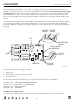
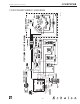
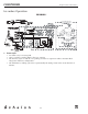
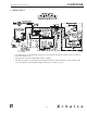
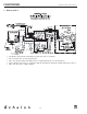
This unit can be put into a diagnostic mode.
1. Unplug unit
2. Install jumper on pins 9 and 10 on board.
3. Plug unit back in.
Based on the information listed below, you can turn on and off each relay individually.
Control pot at 0 – CONDENSER/EVAPORATOR FANS
Jumper on 1/4" spade terminals – COMPRESSOR
Jump pins on J2 – HOT GAS VALVE
Jump pins on J2 – ICEMAKER
Example (force a defrost cycle):
Set control pot to 0, Jump pins on J2 for hot gas valve and install jumper on 1/4" spade terminals.
CLRCO035B
-1
-2
-3
-4
-5
5
4
3
2
1
0
HOT
GAS
COND/EVAP
FAN
ICEMAKER
COMPRESSOR
123456 78910
1/4" SPADE
TERMINALS
POWER ON
POT
POWER
J2
HOT GAS
VALVE
DISPLAY BOARD
CONNECTION
ICEMAKER
SENSOR
FREEZER
SENSOR
9
REFRIGERATOR
SENSOR
ICEMAKER
10
CO2075DWR
42
Design
■
Features
■
Performance