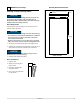
INSTALLATION GUIDE ® MODULAR 3000 SERIES 120V, 3018CLR MODELS U-3018CLROL-00 U-3018CLROL-01 U-3018CLROL-40 U-3018CLROL-41 U-3018CLRS-00 U-3018CLRS-01 U-3018CLRS-40 U-3018CLRS-41 THE MODULAR 3000 SERIES ARE INTENDED FOR BUILT-IN INSTALLATIONS ONLY The American Built-In Undercounter Leader Since 1962 U-LINE.
Table of Contents 1 - Safety Precautions Safety Alert Definitions.........................................................................................................................................1 General Precautions ..............................................................................................................................................1 2 - Inspect & Plan Product Registration ........................................................................................................
General Precautions 1 Safety Precautions Use this appliance for its intended purpose only and follow these general precautions with those listed throughout this guide: NOTICE • PLEASE READ all instructions before installing, operating, or servicing the appliance. • Proper installation procedures must be followed when completing an installation or relocation of a unit. An INSTALLATION GUIDE for the unit, providing complete installation information, is available from U-Line Corporation direct.
Tools/Materials Required 2 Inspect & Plan • Screwdrivers — slotted, Phillips, and T-25 Torx head • Level Product Registration You have received a carton containing your 3000 series unit with a package inside containing a Quick Start Guide and a Registration Card. Please complete and mail the Product Registration Card. You may also register the unit online at u-line.com. Go to the Customer Service tab and click on Product Registration.
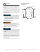
Cut-Out Dimensions 3 Prepare Site 3018CLR Series Your U-Line product has been designed exclusively for a built-in installation. When built-in, your unit does not require additional air space for top, sides, or rear. However, the front grille must NOT be obstructed. Preferred location for 3018CLR drain, water line and receptacle is in adjacent cabinet. The Modular 3000 Series units are engineered with a variety of adjustment features to help ensure a seamless installation.
4 Product Dimensions 3018 Series 23-1/4" 33-11/16" to 34-11/16" 3-5/8" to 4-5/8" 17-3/4" Solid Overlay Door 24" 33-11/16" to 34-11/16" 3-5/8" to 4-5/8" 17-3/4" Stainless Steel Solid Door 4 u-line.
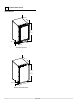
Other Site Requirements 5 Door Swing Dimensions Side-By-Side Installation Units have a zero clearance when the door to open 90°. Overlay models will need additional space for any knobs or pulls installed on the overlay panel / frame. Stainless Steel models require 2" door clearance to accommodate the handle if installed next to a wall. Wall Cut-out width for a side-by-side installation is the total of the widths listed under Cut-Out Dimensions in each unit’s Installation Guide. No trim kit is required.
3. Gently pull bottom of wrap away from door. 6 3000 Series Doors 4. The wrap hinges on top of the door. Carefully pull wrap away and then up. See below. Door Alignment and Adjustment Align and adjust the door if it is not level, or is not sealing properly. If the door is not sealed the unit may not cool properly, or excessive frost or condensation may form in the interior.
7 3000 Series Overlays Overlay Panel Dimensions Overlay / Frame Overlay Panel BACK SURFACE MUST HAVE AMPLE FLAT SURFACE TO MOUNT OVERLAY PANEL FLAT AND WITHOUT INTERFERENCE NOTICE Due to differences in surrounding cabinetry the panel may not perfectly align with door. The procedure below is designed to provide a finished overlay panel that seamlessly integrates with surrounding cabinetry.
NOTICE Make certain the display cable remains securely seated in the inner door channel, see below. Inner Door Channel Display Cable 6. Secure overlay to door using clamps. A robust tape may also be used. U-Line recommends the use of bar clamps to securely clamp the overlay to the door. If using tape be certain the tape will not damage overlay finish upon removal. 7. Using a 7/64" drill bit, drill 6 pilot holes into the wood panel 1/2" (13 mm) deep using the holes in the door frame as a guide. 5.
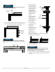
Overlay Grille 1-1/2" A The 3000 series grille is fully adjustable and can be set to match your surrounding cabinetry dimensions. In addition to its adjustability, an overlay may also be installed to truly provide a seamless appearance. Prepare and Install Overlay 1" 1. Use the dimensions provided in the diagram Overlay Grille Dimensions to cut and shape your grille overlay. Recommended overlay thickness is between 1/4" (6.4 mm) and 3/8" (9.5 mm).
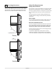
3018CLR Side Mount 8 3000 Series Anti-Tip Bracket Left View Of Cabinet Right View Of Cabinet Anti-Tip Bracket Installation ! CAUTION The anti-tip bracket must be installed to prevent the unit from tipping when doors are fully opened, or excess weight is placed on the front of the unit. The anti-tip bracket has multiple mounting choices, depending on your particular cabinet arrangement. Using the following instructions, secure the anti-tip plate to the unit and then to your cabinets.
9 Installation 9 Level & Install 1. Plug in the power cord. Leveling Information 2. Gently push the unit into position. Be careful to not entangle the electrical cord, water line and drain line. It is recommended that the unit is level once installed. 1. Use a level to check the levelness of the unit from front to back and from side to side. Level should be placed along top edge and side edge as shown. 3. Re-check the leveling, from front to back and side to side. Make any necessary adjustments.
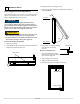
3. Remove front panel of unit. See image below for location of front panel screws. 10 Prepare Plumbing The unit requires a 1/4" O.D. soft copper supply line, or flexible water supply kit from U-Line (Part No. WATERHOOKUP). Remove screws (one on each side) to access behind the front panel ! WARNING Prior to attempting installation, determine if this product contains a gravity style drain or factory installed drain pump. Products without a drain pump may only use a gravity style drain.
8. Locate the U-Line supplied hose fitting. Ensure the end on the copper tubing has been cut straight and is free of burrs. Slide the compression nut and ferrule onto the copper tubing as shown below. 4. Take one end of the braided line and feed it through the front of the unit between the condenser and the right side of the unit. This tubing should be within two inches of the top of the compartment.
11 Drain Connection ! WARNING The 3018CLR requires access to either a gravity or pump fed drain. ! CAUTION If your U-Line unit did not come with a factory installed drain pump you must use a gravity style drain connection. For assistance in determining if your unit has a pump please contact U-Line. The floor drain must be large enough to accommodate drainage from all attached drains.
Final Installation NOTICE The maximum lift for the P60 drain pump is 10 feet. This must be done as close to the rear of the unit as possible. NOTICE Before installing your U-Line 3045CLR with factory-installed U-Line P60 pump, it is extremely important to check and test all hose connections at the drain pump.
INSTALLATION GUIDE ® PRODUCT INFORMATION Complete Installation Guides, Use and Care Guides, Specifications & Features and Benefits, CAD Drawings, Overlay Panel/Frame and Toe-Kick Specifications and Instructions, Compliance Documentation and Applicable Energy Guides are available for reference and download at u-line.com. SERVICE INFORMATION Please consult your Use and Care Guide for troubleshooting information. Answers to Customer Frequently Asked Questions are available at u-line.