USER GUIDE & SERVICE MANUAL SAFETY • INSTALLATION & INTEGRATION • OPERATING INSTRUCTIONS • MAINTENANCE • SERVICE RIGHT PRODUCT. RIGHT PLACE. RIGHT TEMPERATURE. SINCE 1962.
USER GUIDE u-line.
USER GUIDE u-line.com WELCOME TO U-LINE Congratulations on your U-Line purchase. Your product comes from a company with over five decades of premium modular ice making, refrigeration, and wine preservation experience. U-Line continues to be the American leader, delivering versatility and flexibility for multiple applications including residential, light commercial, outdoor and marine use.
USER GUIDE u-line.com SAFETY • INSTALLATION & INTEGRATION • OPERATING INSTRUCTIONS • MAINTENANCE • SERVICE Safety and Warning NOTICE Please read all instructions before installing, operating, or servicing the appliance.
USER GUIDE u-line.com SAFETY • INSTALLATION & INTEGRATION • OPERATING INSTRUCTIONS • MAINTENANCE • SERVICE Disposal and Recycling ! DANGER RISK OF CHILD ENTRAPMENT. Before you throw away your old refrigerator or freezer, take off the doors and leave shelves in place so children may not easily climb inside.
USER GUIDE u-line.com SAFETY • INSTALLATION & INTEGRATION • OPERATING INSTRUCTIONS • MAINTENANCE • SERVICE Environmental Requirements This model is intended for indoor/interior applications only and is not to be used in installations that are open/ exposed to natural elements. This unit is designed to operate between 50°F (10°C) and 100°F (38°C). Higher ambient temperatures may reduce the unit’s ability to reach low temperatures and/or reduce ice production on applicable models.
USER GUIDE u-line.com Electrical ! WARNING SHOCK HAZARD — Electrical Grounding Required. Never attempt to repair or perform maintenance on the unit until the electricity has been disconnected. Never remove the round grounding prong from the plug and never use a two-prong grounding adapter. Altering, cutting or removing power cord, removing power plug, or direct wiring can cause serious injury, fire, loss of property and/or life, and will void the warranty.
USER GUIDE u-line.com SAFETY • INSTALLATION & INTEGRATION • OPERATING INSTRUCTIONS • MAINTENANCE • SERVICE Cutout Dimensions CUTOUT DIMENSIONS PREPARE SITE Your U-Line product has been designed exclusively for a built-in installation. When built-in, your unit does not Preferred location for electrical outlet is in adjacent 5/8" cabinet. (16 mm) require additional air space for top, sides, or rear. However, the front grille must NOT be obstructed.
USER GUIDE u-line.
USER GUIDE u-line.com SAFETY • INSTALLATION & INTEGRATION • OPERATING INSTRUCTIONS • MAINTENANCE • SERVICE Side-by-Side Installation Hinge-by-Hinge Installation (Mullion) When installing two units hinge-by-hinge, 13/16" (22 mm) OTHER SITE REQUIREMENTS is required for integrated models. Additional space may be Side-by-Side Installation needed for any knobs, pulls or handles installed.
USER GUIDE u-line.com SAFETY • INSTALLATION & INTEGRATION • OPERATING INSTRUCTIONS • MAINTENANCE • SERVICE Anti-Tip Bracket SIDE MOUNT Left Hinged Cabinet Right Hinged Cabinet ! CAUTION The anti-tip bracket must be installed to prevent the unit from tipping when doors are fully opened or excess weight is placed on the front of the unit. The anti-tip bracket has multiple mounting options. Mounting will depend on your particular cabinet configuration. Locate 3 #8x5/8" screws included with your unit.
USER GUIDE u-line.com SAFETY • INSTALLATION & INTEGRATION • OPERATING INSTRUCTIONS • MAINTENANCE • SERVICE General Installation INSTALLATION 1. Plug in the power/electrical cord. LEVELING INFORMATION 1. Use a level to confirm 2. Gently push the unit into position. Be careful not to the unit is level. Level entangle the cord. should be placed along top edge and side 3. Re-check the leveling, from front to back and side to 1 edge as shown. side. Make any necessary adjustments.
USER GUIDE u-line.com SAFETY • INSTALLATION & INTEGRATION • OPERATING INSTRUCTIONS • MAINTENANCE • SERVICE Integrated Grille - Plinth Dimensions 3-5/16" to 4-5/16" (84 mm to 110 mm) INTEGRATED GRILLE (PLINTH STRIP/BASE FASCIA) DIMENSIONS PREPARE AND INSTALL INTEGRATED GRILLE (PLINTH STRIP/BASE FASCIA) 1. Use the dimensions provided in the diagram to cut and 1-9/16" (40 mm) shape your integrated grille (plinth strip/base fascia) panel.
USER GUIDE u-line.com SAFETY • INSTALLATION & INTEGRATION • OPERATING INSTRUCTIONS • MAINTENANCE • SERVICE Grille - Plinth Installation Installing the grille (plinth strip/base fascia) REMOVING AND INSTALLING GRILLE (PLINTH STRIP/BASE FASCIA) 1. Align slots in grille (plinth strip/base fascia) rail with screw heads in base of unit ! WARNING 2. Push grille (plinth strip/base fascia) rails towards the center of the unit and set rails over screw head.
USER GUIDE u-line.com SAFETY • INSTALLATION & INTEGRATION • OPERATING INSTRUCTIONS • MAINTENANCE • SERVICE Door Swing Stainless Steel models that are installed adjacent to a wall require 2-1/4” (57 mm) door clearance on hinge side to allow for door handle. Units have a zero clearance when installed adjacent to cabinets.
USER GUIDE u-line.com SAFETY • INSTALLATION & INTEGRATION • OPERATING INSTRUCTIONS • MAINTENANCE • SERVICE Door Stop 3. Once cover is removed, slide hinge pin into hole as shown. Pin should slide into place, stopping the door at Your U-Line unit was shipped to you with the optional 90° 90°; if the pin does not go into the hole shown, hold pin. the door less than 90° open and try again. Your unit’s door(s) will open 115° straight from the factory.
USER GUIDE u-line.com SAFETY • INSTALLATION & INTEGRATION • OPERATING INSTRUCTIONS • MAINTENANCE • SERVICE Door Adjustments DOOR ALIGNMENT AND ADJUSTMENT Align and adjust the door if it is not level or is not sealing properly. If the door is not sealed, the unit may not cool T-25 Torx Screw properly, or excessive frost or condensation may form in the interior. NOTICE Properly aligned, the door’s gasket should be firmly in contact with the cabinet all the way T-25 Torx Screw around the door (no gaps).
USER GUIDE u-line.com SAFETY • INSTALLATION & INTEGRATION • OPERATING INSTRUCTIONS • MAINTENANCE • SERVICE 3. Using T-25 Torx bit loosen screw #1 and remove screw #2 on top and bottom hinge. Slide and remove the door from unit. Completely remove screw #1 on top and bottom. 2 1 4. Remove caps from screw heads on opposite side (2 on top and 2 on bottom). Using #2 Phillips bit remove the 4 underlying screws. Reinstall the screws and caps on the opposite side. 5.
USER GUIDE u-line.com SAFETY • INSTALLATION & INTEGRATION • OPERATING INSTRUCTIONS • MAINTENANCE • SERVICE First Use All U-Line controls are preset at the factory. Initial startup requires no adjustments. NOTICE U-Line recommends allowing the unit to run overnight before loading with product. When plugged in, the unit will begin operating under the factory default setting. Follow the on screen prompt for language selection and temperature units.
USER GUIDE u-line.com SAFETY • INSTALLATION & INTEGRATION • OPERATING INSTRUCTIONS • MAINTENANCE • SERVICE Control Operation Up Zone Toggle Select Polar O°F Down Can be displayed in Celsius Power U-Select Lighting CONTROL FUNCTION GUIDE FUNCTION COMMAND DISPLAY/OPTIONS OFF Press and hold Display will count down from 5 to off. ON Press and release Unit will come on immediately.
USER GUIDE u-line.com SAFETY • INSTALLATION & INTEGRATION • OPERATING INSTRUCTIONS • MAINTENANCE • SERVICE U-SELECT® CONTROL 3. Press to cycle through each available timer setting. Digital Display Selections include “On With Door”, “On 3 Hours”, “On 6 The 3000 Series units are controlled by a feature rich, Hours”, or “On 24 Hours”. advanced OLED display control unit. The control panel allows adjustment to temperature set point, access to 4.
USER GUIDE u-line.com SAFETY • INSTALLATION & INTEGRATION • OPERATING INSTRUCTIONS • MAINTENANCE • SERVICE CUSTOMER MENU 2. Press or to scroll through available information. The 3000 Series of U-Line undercounter refrigeration appliances contains a feature rich customer menu. The 3. To return to the Customer Menu, press Customer Menu allows access to a series of advanced and select “Return to Menu”.
USER GUIDE u-line.com SAFETY • INSTALLATION & INTEGRATION • OPERATING INSTRUCTIONS • MAINTENANCE • SERVICE Languages 2. Press . The current setting will begin to flash. Up Select RETURN TO MENU LANGUAGES ENGLISH 3. Press or to select a different level. 4. Press to confirm your choice. Down The U-Line 3000 Series of models supports a number of Fahrenheit/Celsius display languages including English, Spanish, French and Up German. Select RETURN TO MENU FARENHEIT/CELSIUS DEGREES = °F 1.
USER GUIDE u-line.com SAFETY • INSTALLATION & INTEGRATION • OPERATING INSTRUCTIONS • MAINTENANCE • SERVICE Factory Default Help Up Up Select Select RETURN TO MENU Help Model 3045WC 1-800-779-2547 RETURN TO MENU FACTORY DEFAULT RESTORE? Down Down Factory Default will restore all settings to their factory To access the Help Menu, select Help from the Customer default. Menu. Press or to scroll through available information. The Help screen displays the following: To access Factory Default: 1.
USER GUIDE u-line.com SAFETY • INSTALLATION & INTEGRATION • OPERATING INSTRUCTIONS • MAINTENANCE • SERVICE L Sabbath Mode 7. Press or to change “Off” to “On”. 8. Press to confirm your selection. The Display will fade out as the unit enters Sabbath Mode. Up Select Sabbath RETURN TO MENU SABBATH MODE OFF? Mode remains active until is quickly pressed and released. Down This unit offers a Sabbath mode for users who require this functionality during Sabbaths.
USER GUIDE u-line.com SAFETY • INSTALLATION & INTEGRATION • OPERATING INSTRUCTIONS • MAINTENANCE • SERVICE Airflow and Product Loading NOTICE The unit requires proper airflow to perform at its highest efficiency. Do not block the front grille, internal fans or vents at any time, or the unit will not perform as expected. Do not install the unit behind a door.
USER GUIDE u-line.com SAFETY • INSTALLATION & INTEGRATION • OPERATING INSTRUCTIONS • MAINTENANCE • SERVICE Freezer Baskets Cleaning Baskets may be cleaned in a soapy warm water solution. FREEZER BASKET INSTALLATION & REMOVAL A general household disinfectant, safe for plastics, may be Freezer baskets are easily removed for cleaning. To used if necessary. Be sure to completely dry your basket before reinstalling. remove the baskets follow the instructions below.
USER GUIDE u-line.com SAFETY • INSTALLATION & INTEGRATION • OPERATING INSTRUCTIONS • MAINTENANCE • SERVICE Cleaning Integrated Models To clean integrated panels, use household cleaner per the EXTERIOR CLEANING cabinet manufacturer’s recommendation. Stainless Models Stainless door panels and handles can discolor when INTERIOR CLEANING exposed to chlorine gas, pool chemicals, saltwater or Disconnect power to the unit. cleaners with bleach.
USER GUIDE u-line.com SAFETY • INSTALLATION & INTEGRATION • OPERATING INSTRUCTIONS • MAINTENANCE • SERVICE NOTICE The drain pan was not designed to capture the water created when manually defrosting. To prevent water from overflowing the drain pan and possibly damaging water sensitive flooring, the unit must be removed from cabinetry. To defrost: 1. Disconnect power to the unit. 2. Remove all products from the interior. 3. Prop the door in an open position (2 in. [50 mm] minimum). 4.
USER GUIDE u-line.com SAFETY • INSTALLATION & INTEGRATION • OPERATING INSTRUCTIONS • MAINTENANCE • SERVICE Cleaning Condenser INTERVAL - EVERY SIX MONTHS To maintain operational efficiency, keep the front grille (plinth strip/base fascia) free of dust and lint, and clean the condenser when necessary. Depending on environmental conditions, more or less frequent cleaning may be necessary. ! WARNING Disconnect electric current to the unit before cleaning the condenser.
USER GUIDE u-line.com SAFETY • INSTALLATION & INTEGRATION • OPERATING INSTRUCTIONS • MAINTENANCE • SERVICE Extended Non-Use VACATION/HOLIDAY, PROLONGED SHUTDOWN The following steps are recommended for periods of extended non-use: 1. Remove all consumable content from the unit. 2. Disconnect the power cord from its outlet/socket and leave it disconnected until the unit is returned to service. 3. If ice is on the evaporator, allow ice to thaw naturally. 4. Clean and dry the interior of the unit.
USER GUIDE u-line.com SAFETY • INSTALLATION & INTEGRATION • OPERATING INSTRUCTIONS • MAINTENANCE • SERVICE Troubleshooting • Evaporator: Refrigerant flowing through an evaporator may sound like boiling liquid. BEFORE CALLING FOR SERVICE If you think your U-Line product is malfunctioning, read • Condenser Fan: Air moving through a condenser may the CONTROL OPERATION section to clearly understand be heard. the function of the control.
USER GUIDE u-line.com SAFETY • INSTALLATION & INTEGRATION • OPERATING INSTRUCTIONS • MAINTENANCE • SERVICE Problem Possible Cause and Remedy Product Is Not Cold Enough. Air temperature does not indicate product temperature. See CHECKING PRODUCT TEMPERATURE below. Adjust the temperate to a cooler set point. Ensure unit is not located in excessive ambient temperatures or in direct sunlight. Ensure the door is closing and sealing properly. Ensure the interior light has not remained on too long.
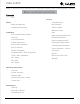
R/B LIGHT L/T LIGHT EVAP TEMP COND FAN L/T DOOR SWITCH R/B DOOR SWITCH AMBIENT TEMP ZONE TEMP EVAP TEMP NA EN 5 1 6 10 8 1 16 9 J9 J10 T AN OG CONTROL BOARD PR G TO IN RA M FUSE 10 1 OPEN Y 42357_B WIRING DIAGRAM LA DI SP LIGHT BLUE (TO COMPRESSOR) DRAIN TUBE HEATER 115 VOLT NEUTRAL: WHITE (115v) DARK BLUE (220-240v) ORANGE VALVE BLUE RELAY HOT: BLACK (115v) BROWN (220-240v) 115 VOLT PLUG PLUG 220-240 VOLT 220-240 VOLT CAP.
USER GUIDE u-line.com SAFETY • INSTALLATION & INTEGRATION • OPERATING INSTRUCTIONS • MAINTENANCE • SERVICE Product Liability Field service technicians are authorized to make an initial assessment in the event of reported damages. If there are any questions about the process involved, the technician should call U-Line for further explanation. While inspecting for defects or installation issues, photos should be taken to document any damages or issues found.
USER GUIDE u-line.com SAFETY • INSTALLATION & INTEGRATION • OPERATING INSTRUCTIONS • MAINTENANCE • SERVICE Warranty Claims warranty status.
Parts 18 1 26 17 7 U-3024FZRS-00B Item 12 27 33 21 13 14 32 29 30 28 Description U-Line P/N 1 Anti tip bracket w/screws 80-54012-00 2 Back panel 80-54107-00 3 Compressor electricals only 80-54167-00 4 Compressor w/electricals 80-54166-00 5 Condenser 80-54043-00 6 Condenser fan w/screws 80-54106-00 7 Display module 80-54032-00 8 Door assembly w/ hinges 80-54170-00 9 Door gasket 80-54039-00 10 Drain pan w/double sided tape 80-54002-00 11 Drier 80-54055-00 12 Evap fa
USER GUIDE u-line.com SAFETY • INSTALLATION & INTEGRATION • OPERATING INSTRUCTIONS • MAINTENANCE • SERVICE Ordering Replacement Parts If you have a purchasing account, please utilize our service website to order parts. Orders may also be placed by Fax or phone. See our contact information below: www.U-LineService.com (with service login) FAX Number: +1.414.354.5696 Phone Number: +1.800.779.2547 NOTICE Use only genuine U-Line replacement parts.
USER GUIDE u-line.com SAFETY • INSTALLATION & INTEGRATION • OPERATING INSTRUCTIONS • MAINTENANCE • SERVICE R-600A Specifications Gloves and Eye Protection must be used. For R-600a refrigerant service tips and more videos, go to: www.u-line.com/videos. ! WARNING Flammability warnings for a pure-iso-butane refrigerant. R-600a is considered non-toxic, but is flammable when mixed with air. Keep a dry powder type fire extinguisher in the work area.
USER GUIDE u-line.com SAFETY • INSTALLATION & INTEGRATION • OPERATING INSTRUCTIONS • MAINTENANCE • SERVICE R-600A SPECIFICATIONS/LABELING ! WARNING R-600a equipped products are labeled (both the unit and the compressor). Only skilled and well trained service technicians permitted to service R-600a equipped products. R-600a is colorless and odorless. All tools and equipment must be approved for R-600a is considered non-toxic, but is flammable when use with R-600a refrigerant. mixed with air.
USER GUIDE u-line.com SAFETY • INSTALLATION & INTEGRATION • OPERATING INSTRUCTIONS • MAINTENANCE • SERVICE Evacuate/reclaim via the piecing pliers to ensure the When re-brazing, the system must be purged with dry system is empty of R-600a before any system work is nitrogen and at least one access point open to the performed. atmosphere. When re-brazing, proper ventilation is required along with constant monitoring for the presence of R600a refrigerant.
USER GUIDE u-line.com SAFETY • INSTALLATION & INTEGRATION • OPERATING INSTRUCTIONS • MAINTENANCE • SERVICE Proper ventilation during service is required. The low side of the refrigeration system (evaporator, compressor and suction line) must be leak tested with the compressor off (equalized pressure). Never apply a torch to a charged R-600a refrigeration system.
USER GUIDE u-line.
USER GUIDE u-line.com SAFETY • INSTALLATION & INTEGRATION • OPERATING INSTRUCTIONS • MAINTENANCE • SERVICE Compressor Specifications OVERLOAD PROTECTOR STARTING RELAY ! DANGER C S Electrocution can cause death or serious injury. R Burns from hot or cold surfaces can cause RELAY COVER serious injury. Take precautions when servicing CAPACITOR this unit. Electrical Relay and Overload Protector Disconnect the power source.
USER GUIDE u-line.com SAFETY • INSTALLATION & INTEGRATION • OPERATING INSTRUCTIONS • MAINTENANCE • SERVICE Troubleshooting - Extended SPECIFIC ERRORS AND ISSUES The technically advanced diagnostic capabilities of the electronic controls utilized on the 3000 series units allows for easy and thorough trouble shooting.
USER GUIDE u-line.com SAFETY • INSTALLATION & INTEGRATION • OPERATING INSTRUCTIONS • MAINTENANCE • SERVICE TROUBLESHOOTING GUIDE Concern Potential Causes Suggested Remedy Not Cooling Compressor overheating Verify proper air flow through condenser (Refer to Airflow/General Information Section). Confirm condenser fan operation (Refer to Airflow/General Information Section). Confirm proper compressor operating voltage (Refer to Toggle/ Compressor Information Section).
USER GUIDE u-line.com SAFETY • INSTALLATION & INTEGRATION • OPERATING INSTRUCTIONS • MAINTENANCE • SERVICE MAIN CONTROL Testing The Main Control The main control board is very robust and is rarely the If the main control is suspected of being faulty, the cause of system issues. It is important to fully diagnose following procedure should be performed to verify main the board for any suspected failures before attempting to control for functionality. remove the board for replacement or service.
USER GUIDE u-line.com SAFETY • INSTALLATION & INTEGRATION • OPERATING INSTRUCTIONS • MAINTENANCE • SERVICE Other Suspected Main Control Faults NOTE: If the unit is set to sabbath mode the evaporator If other components have been ruled out as being faulty fan will no longer respond to the state of the door switch. but the unit continues to have operating issues, it is most In order to operate efficiently the evaporator fan blade likely due to a configuration error.
USER GUIDE u-line.com SAFETY • INSTALLATION & INTEGRATION • OPERATING INSTRUCTIONS • MAINTENANCE • SERVICE FAULT SYSTEM DIAGNOSIS GUIDE Error Solution 1 Solution 2 No Comm Inspect Customer UI and Data Cable (if defective replace entire door) Zone T Open Inspect zone thermistor connection. Replace if necessary. Inspect main control wire harness for splits or breaks. Repair split or cut cabling. Evap T Open Inspect evaporator thermistor connection. Replace if necessary.
USER GUIDE u-line.com SAFETY • INSTALLATION & INTEGRATION • OPERATING INSTRUCTIONS • MAINTENANCE • SERVICE THERMISTORS REED SWITCH Thermistors are used for various temperature readings. A reed switch is used to monitor door state. When the Thermistors provide reliable temperature readings using a door is closed magnetic force pulls the reed to its contact resistance which varies based on surrounding and closes the circuit which turns the light and display off. temperatures.
USER GUIDE u-line.
USER GUIDE u-line.com SAFETY • INSTALLATION & INTEGRATION • OPERATING INSTRUCTIONS • MAINTENANCE • SERVICE SERVICE MENU The All Errors option keeps record of any system errors. In addition to a feature rich customer menu, the 3000 When an error occurs it is recorded to all errors. The series also offers a service menu with the ability to fine number next to the error indicates the number of recorded tune and monitor unit operation. instances. Errors in the log may not be currently active.
USER GUIDE u-line.com SAFETY • INSTALLATION & INTEGRATION • OPERATING INSTRUCTIONS • MAINTENANCE • SERVICE Relay Status ID Description Solution Amb Thrm Short Ambient thermistor circuit shorted. Check thermistor connection to harness for moisture or corrosion. Also check connection where thermistor harness attaches to main board. If connections are valid replace the thermistor. Temp Hi 6H+ Temp Hi 12H+ Zone temperature +10°F over set point for over 6 hours.
USER GUIDE u-line.com SAFETY • INSTALLATION & INTEGRATION • OPERATING INSTRUCTIONS • MAINTENANCE • SERVICE Input Status Relay Toggle Up Up Select Select RETURN TO MENU RELAY TOGGLE MULL OFF COND OFF RETURN TO MENU INPUT STATUS DOOR OPEN IN2 OPEN Down Down Relay toggle is used to manually switch the state of each Input status displays the current state of each available relay to test for proper operation. In addition to the AC input. relays, DC switches may also be toggled.
USER GUIDE u-line.com SAFETY • INSTALLATION & INTEGRATION • OPERATING INSTRUCTIONS • MAINTENANCE • SERVICE 3. Press To access Outputs 1. Press and to scroll through available thermistors. to select “Outputs”. To change offsets 2. Press 3. Press 4. Press . and to scroll through available , the selected thermistor will begin to flash. 5. Press or to modify offset value. 6. Press to confirm setting. information.
USER GUIDE u-line.
USER GUIDE u-line.com SAFETY • INSTALLATION & INTEGRATION • OPERATING INSTRUCTIONS • MAINTENANCE • SERVICE Re-Select Model allows the units model information to be Factory Default modified. Changing the units model completely Up reprograms available zones, relay assignments, DC output Select assignments etc. RETURN TO MENU FACTORY DEFAULT RESTORE? To access Re-Select Model 1. Press Down Factory Default will restore all settings to their factory 2. Press default. to select “Re-Select Model”. .
USER GUIDE u-line.com SAFETY • INSTALLATION & INTEGRATION • OPERATING INSTRUCTIONS • MAINTENANCE • SERVICE The Fan Delay menu option allows the modification of fan run times during and after a cooling cycle. In order to allow time for the evaporator to properly cool, the evaporator fan is delayed from starting with the cooling cycle for a given amount of time.
USER GUIDE u-line.com SAFETY • INSTALLATION & INTEGRATION • OPERATING INSTRUCTIONS • MAINTENANCE • SERVICE To toggle showroom mode 1. Press to select “Showroom Mode”. 2. Press . 3. Press flash. to select “Off” and press 4. Press or 5. Press to confirm. . “Off” will begin to to toggle between off and on. If set to “on” showroom mode will begin immediately. To exit showroom mode press and hold for 5 seconds and release. The display will show a countdown to switching the unit off.
USER GUIDE u-line.com SAFETY • INSTALLATION & INTEGRATION • OPERATING INSTRUCTIONS • MAINTENANCE • SERVICE Thermistors Thermistor three (Ambient): Located in the base of the unit (secured to the Thermistors are used for various temperature readings. condenser). It is used to monitor the ambient temperature Thermistors provide reliable temperature readings using a within the base compartment. It is used for diagnostics. resistance which varies based on surrounding temperatures.
USER GUIDE u-line.
USER GUIDE u-line.com SAFETY • INSTALLATION & INTEGRATION • OPERATING INSTRUCTIONS • MAINTENANCE • SERVICE Defrost The models below have automatic or frost free design and do not require manual defrosting under normal conditions.
USER GUIDE u-line.com SAFETY • INSTALLATION & INTEGRATION • OPERATING INSTRUCTIONS • MAINTENANCE • SERVICE Remove Fan and Cover Evaporator Fan Replacement Should the evaporator fan need to be replaced follow the CONVECTION COOLING steps below. This unit is equipped with an advanced convection cooling system. Convection cooling stabilizes cabinet 1. Remove any product from the unit. temperature, cools product faster and increases energy efficiency. 2. Uninstall unit. Evaporator Fan 3.
USER GUIDE u-line.com SAFETY • INSTALLATION & INTEGRATION • OPERATING INSTRUCTIONS • MAINTENANCE • SERVICE 11.Grasp evaporator cover, pull the top forward and up as bottom of cover is installed behind the front edge of the drain trough. 12.While pulling the evaporator cover clear of the unit, it may be necessary to use your free hand to manipulate the fan plug end through the pass-through hole. 13.Remove the 4 screws mounting the fan shroud to the evaporator plate. Air Flow 14.Remove and replace fan.
USER GUIDE u-line.com SAFETY • INSTALLATION & INTEGRATION • OPERATING INSTRUCTIONS • MAINTENANCE • SERVICE U-Line Corporation (U-Line) Limited Warranty One Year Limited Warranty For one year from the date of original purchase, this U-Line product warranty covers all parts and labor to repair or replace any part of the product that proves to be defective in materials or workmanship.