USER GUIDE & SERVICE MANUAL SAFETY • INSTALLATION & INTEGRATION • OPERATING INSTRUCTIONS • MAINTENANCE • SERVICE RIGHT PRODUCT. RIGHT PLACE. RIGHT TEMPERATURE. SINCE 1962.
USER GUIDE u-line.
USER GUIDE u-line.com WELCOME TO U-LINE Congratulations on your U-Line purchase. Your product comes from a company with over five decades of premium modular ice making, refrigeration, and wine preservation experience. U-Line continues to be the American leader, delivering versatility and flexibility for multiple applications including residential, light commercial, outdoor and marine use.
USER GUIDE u-line.com SAFETY • INSTALLATION & INTEGRATION • OPERATING INSTRUCTIONS • MAINTENANCE • SERVICE Safety and Warning that they do not play with this appliance. Cleaning and user maintenance shall not be performed by children without supervision. NOTICE PLEASE READ all instructions before installing, operating, or servicing the appliance. ! DANGER Do not use electrical appliances inside the food SAFETY ALERT DEFINITIONS storage compartment of this appliance.
USER GUIDE u-line.com SAFETY • INSTALLATION & INTEGRATION • OPERATING INSTRUCTIONS • MAINTENANCE • SERVICE • Staff kitchen areas in shops, office and other working ! CAUTION environments. Use care when moving and handling the unit. • Farm houses and by clients in hotels, motels and other Use gloves to prevent personal injury from sharp residential type environments. edges. • Bed and breakfast type environments.
USER GUIDE u-line.com SAFETY • INSTALLATION & INTEGRATION • OPERATING INSTRUCTIONS • MAINTENANCE • SERVICE Disposal and Recycling ! DANGER RISK OF CHILD ENTRAPMENT. Before you throw away your old refrigerator or freezer, take off the doors and leave shelves in place so children may not easily climb inside.
USER GUIDE u-line.com SAFETY • INSTALLATION & INTEGRATION • OPERATING INSTRUCTIONS • MAINTENANCE • SERVICE Environmental Requirements This model is intended for indoor/interior applications only and is not to be used in installations that are open/ exposed to natural elements. This unit is designed to operate between 50°F (10°C) and 90°F (32°C). Higher ambient temperatures may reduce the unit’s ability to reach low temperatures and/or reduce ice production on applicable models.
USER GUIDE u-line.com SAFETY • INSTALLATION & INTEGRATION • OPERATING INSTRUCTIONS • MAINTENANCE • SERVICE Electrical NOTICE Electrical installation must observe all state and ! WARNING local codes. This unit requires connection to a grounded (three-prong), polarized receptacle SHOCK HAZARD — Electrical Grounding that has been placed by a qualified electrician. Required.
USER GUIDE u-line.com SAFETY • INSTALLATION & INTEGRATION • OPERATING INSTRUCTIONS • MAINTENANCE • SERVICE Cutout Dimensions CUTOUT DIMENSIONS PREPARE SITE Your U-Line product has been designed exclusively for a built-in installation. When built-in, your unit does not Preferred location for drain, water line and receptacle is in adjacent 5/8" cabinet. (16 mm) require additional air space for top, sides, or rear. However, the front grille (plinth strip/base fascia) must NOT be obstructed.
USER GUIDE u-line.
USER GUIDE u-line.com SAFETY • INSTALLATION & INTEGRATION • OPERATING INSTRUCTIONS • MAINTENANCE • SERVICE Side-by-Side Installation Hinge-by-Hinge Installation (Mullion) When installing two units hinge-by-hinge, 13/16" (22 mm) OTHER SITE REQUIREMENTS is required for integrated models. Additional space may be Side-by-Side Installation needed for any knobs, pulls or handles installed.
USER GUIDE u-line.com SAFETY • INSTALLATION & INTEGRATION • OPERATING INSTRUCTIONS • MAINTENANCE • SERVICE Water Hookup ! CAUTION PREPARE PLUMBING Do not use any plastic water supply line. The line The water valve uses a standard 1/4" (6.35 mm) is under pressure at all times. Plastic may crack compression fitting. U-Line recommends using accessory or rupture with age and cause damage to your water hook up kit – part # 80-54674-00. The kit includes a home.
USER GUIDE u-line.com SAFETY • INSTALLATION & INTEGRATION • OPERATING INSTRUCTIONS • MAINTENANCE • SERVICE 3. Locate water 8. Install retaining clip. valve in the front of the unit and thread water supply line through. NOTICE Route the water supply line through the unit so it does not come into contact with any internal components other than the solenoid valve. Normal operation creates some vibration.
USER GUIDE u-line.com SAFETY • INSTALLATION & INTEGRATION • OPERATING INSTRUCTIONS • MAINTENANCE • SERVICE Drain GRAVITY DRAIN Model numbers including “-00” or “-07” do not include a factory installed drain pump. Normal Proper Drain Model numbers including “-40” or “-47” include a factory installed drain pump.
USER GUIDE u-line.com SAFETY • INSTALLATION & INTEGRATION • OPERATING INSTRUCTIONS • MAINTENANCE • SERVICE FACTORY INSTALLED DRAIN PUMP Y-Branch Tailpiece P60 Pump Required If your drain line will run up to a stand pipe, disposal or Air Gap (Optional Hook-Up) spigot assembly, or does not otherwise meet the requirements for a gravity drain, you may have ordered a pre-installed U-Line P60 drain pump.
USER GUIDE u-line.com SAFETY • INSTALLATION & INTEGRATION • OPERATING INSTRUCTIONS • MAINTENANCE • SERVICE Drain Pump INCLUDED IN KIT: 1. 1x S-shaped Drain Tube NOTICE PLEASE READ this instruction completely before 1 2. 1x Straight Drain Tube attempting to install or operate the unit. Improper hook-up can result in substantial property damage! If you are unsure of your ability to safely connect the drain pump to the (Not used) 2 3. 1x Vent Tube 3 unit, consult a licensed plumber for assistance.
USER GUIDE u-line.com SAFETY • INSTALLATION & INTEGRATION • OPERATING INSTRUCTIONS • MAINTENANCE • SERVICE Note: Slide clamp on hose end before installing hose. Do not 8 tighten clamp until pump and hoses have been installed. 4. Install the 3 hoses and hose clamps to the pump assembly Wiring Plug as shown below. Do not tighten Ground Terminal clamps at this time.
USER GUIDE u-line.com SAFETY • INSTALLATION & INTEGRATION • OPERATING INSTRUCTIONS • MAINTENANCE • SERVICE Note: The discharge tube will need to be trimmed. Cut ! WARNING back the tube (MAX of 1/4" on each end) so that no kinks are formed in drain tube. The back panel serves as a guard. Do not put your hands inside the ice machine cabinet or attempt to touch any components except the discharge tube during testing.
USER GUIDE u-line.com SAFETY • INSTALLATION & INTEGRATION • OPERATING INSTRUCTIONS • MAINTENANCE • SERVICE Anti-Tip Bracket SIDE MOUNT Left Hinged Cabinet Right Hinged Cabinet ! CAUTION The anti-tip bracket must be installed to prevent the unit from tipping when doors are fully opened or excess weight is placed on the front of the unit. The anti-tip bracket has multiple mounting options. Mounting will depend on your particular cabinet configuration. Locate 3 #8x5/8" screws included with your unit.
USER GUIDE u-line.com SAFETY • INSTALLATION & INTEGRATION • OPERATING INSTRUCTIONS • MAINTENANCE • SERVICE General Installation INSTALLATION 1. Plug in the power/electrical cord. 1. Use a level to confirm the unit is level. Level 2. Gently push the unit into position. Be careful not to should be placed along top edge and side entangle the cord or water and drain lines. 1 edge as shown. 3. Re-check the leveling, from front to back and side to side. Make any necessary adjustments. The unit’s top 2.
USER GUIDE u-line.com SAFETY • INSTALLATION & INTEGRATION • OPERATING INSTRUCTIONS • MAINTENANCE • SERVICE Integrated Panel Dimensions Integrated Panel Dimensions Metric measurements rounded and optimized. BACK SURFACE MUST HAVE AMPLE FLAT SURFACE TO MOUNT OVERLAY PANEL FLAT AND WITHOUT INTERFERENCE 3/4" INTEGRATED PANEL (20 mm) NOTICE 17-5/8" (445 mm) Due to differences in surrounding cabinetry the panel may not perfectly align with door.
USER GUIDE u-line.com SAFETY • INSTALLATION & INTEGRATION • OPERATING INSTRUCTIONS • MAINTENANCE • SERVICE 3. Prepare the insert(s) that will back up the handleless HANDLELESS INTEGRATED DOOR PANEL The following procedure is designed to provide a finished, design. Wooden Insert – Cut 1/8" (3 mm) thick handleless solid panel for an 18" (450 mm) door that wooden insert(s) to the dimensions below. seamlessly integrates with its surrounding cabinetry.
USER GUIDE u-line.com SAFETY • INSTALLATION & INTEGRATION • OPERATING INSTRUCTIONS • MAINTENANCE • SERVICE Handleless Integrated Panel Dimensions 1/8" (3 mm) Top Design 1/4" (6 mm) 7/8" (22 mm) Ref.
USER GUIDE u-line.com SAFETY • INSTALLATION & INTEGRATION • OPERATING INSTRUCTIONS • MAINTENANCE • SERVICE EXTENDED INTEGRATED PANEL NOTICE Due to differences in surrounding cabinetry the panel may not perfectly align with door. The procedure below is designed to provide a finished panel that seamlessly integrates with surrounding cabinetry. Panel Preparation An extended integrated panel can be used to maintain alignment with an adjacent extended cabinet height or a reduced toe-kick/grille application.
USER GUIDE u-line.com SAFETY • INSTALLATION & INTEGRATION • OPERATING INSTRUCTIONS • MAINTENANCE • SERVICE Front Side Integrated Panel/Integrated Frame Integrated Panel U-Line Unit Cabinet U-Line Unit 3-5/16" (89 mm) to 4-5/16" (114 mm) > 3-5/16" (> 89 mm) 3-5/16" (89 mm) to 4-5/16" (114 mm) Floor Front Side Extended Integrated Panel/Extended Integrated Frame U-Line Unit Cabinet Integrated Panel U-Line Unit * Panel can extend beyond the door frame.
USER GUIDE u-line.com SAFETY • INSTALLATION & INTEGRATION • OPERATING INSTRUCTIONS • MAINTENANCE • SERVICE Extended Integrated Panel Dimensions BACK SURFACE MUST HAVE AMPLE FLAT SURFACE TO MOUNT INTEGRATED PANEL FLAT AND 3/4" WITHOUT INTERFERENCE (20 mm) 17-5/8" (445 mm) 30.0" 33-7/8" (762 mm 860 mm)* Integrated Panel * A minimum of 1" (25 mm) is required from the floor to the bottom of the extended integrated panel/frame for proper ventilation.
USER GUIDE u-line.com SAFETY • INSTALLATION & INTEGRATION • OPERATING INSTRUCTIONS • MAINTENANCE • SERVICE Integrated Grille - Plinth Dimensions 3-5/16" to 4-5/16" (84 mm to 110 mm) INTEGRATED GRILLE (PLINTH STRIP/BASE FASCIA) DIMENSIONS PREPARE AND INSTALL INTEGRATED GRILLE (PLINTH STRIP/BASE FASCIA) 1. Use the dimensions provided in the diagram to cut and 1-9/16" (40 mm) shape your integrated grille (plinth strip/base fascia) panel.
USER GUIDE u-line.com SAFETY • INSTALLATION & INTEGRATION • OPERATING INSTRUCTIONS • MAINTENANCE • SERVICE Integrated Panel Installation NOTICE 1. Fully open door. It is important to ensure that all drilled holes are drilled to the correct depth in order to avoid splits in the wood when hardwood is installed. 2. Starting at corner, pull gasket away from door. 8. Locate 6 of the #6x 1-1/2" (38 mm) screws provided with your unit. 3. Continue to pull gasket free from gasket channel. 9.
USER GUIDE u-line.com SAFETY • INSTALLATION & INTEGRATION • OPERATING INSTRUCTIONS • MAINTENANCE • SERVICE Grille - Plinth Installation Installing the grille (plinth strip/base fascia) REMOVING AND INSTALLING GRILLE (PLINTH STRIP/BASE FASCIA) 1. Align slots in grille (plinth strip/base fascia) rail with screw heads in base of unit ! WARNING 2. Push grille (plinth strip/base fascia) rails towards the center of the unit and set rails over screw head.
USER GUIDE u-line.com SAFETY • INSTALLATION & INTEGRATION • OPERATING INSTRUCTIONS • MAINTENANCE • SERVICE Door Swing For models that are installed adjacent to a wall, 1/2" (13 mm) clearance is recommended from wall on hinge side to allow the door to open 90°. Allow for additional space for any knobs or pulls installed on the integrated panel/frame. Units have a zero clearance when installed adjacent to cabinets.
USER GUIDE u-line.com SAFETY • INSTALLATION & INTEGRATION • OPERATING INSTRUCTIONS • MAINTENANCE • SERVICE Door Stop 3. Once cover is removed, slide hinge pin into hole as shown. Pin should slide into place, stopping the door at Your U-Line unit was shipped to you with the optional 90° 90°; if the pin does not go into the hole shown, hold pin. the door less than 90° open and try again. Your unit’s door(s) will open 115° straight from the factory.
USER GUIDE u-line.com SAFETY • INSTALLATION & INTEGRATION • OPERATING INSTRUCTIONS • MAINTENANCE • SERVICE Door Adjustments DOOR ALIGNMENT AND ADJUSTMENT Align and adjust the door if it is not level or is not sealing properly. If the door is not sealed, the unit may not cool T-25 Torx Screw properly, or excessive frost or condensation may form in the interior. NOTICE Properly aligned, the door’s gasket should be firmly in contact with the cabinet all the way T-25 Torx Screw around the door (no gaps).
USER GUIDE u-line.com SAFETY • INSTALLATION & INTEGRATION • OPERATING INSTRUCTIONS • MAINTENANCE • SERVICE 3. Using T-25 Torx bit loosen screw #1 and remove screw #2 on top and bottom hinge. Slide and remove the door from unit. Completely remove screw #1 on top and bottom. 2 1 4. Remove caps from screw heads on opposite side (2 on top and 2 on bottom). Using #2 Phillips bit remove the 4 underlying screws. Reinstall the screws and caps on the opposite side. 5.
USER GUIDE u-line.com SAFETY • INSTALLATION & INTEGRATION • OPERATING INSTRUCTIONS • MAINTENANCE • SERVICE First Use All U-Line controls are preset at the factory. Initial startup requires no adjustments. NOTICE U-Line recommends discarding the ice produced during the first two to three hours of operation to avoid possible dirt or scale that may dislodge from the water line. When plugged in, the unit will begin operating under the factory default setting.
USER GUIDE u-line.com SAFETY • INSTALLATION & INTEGRATION • OPERATING INSTRUCTIONS • MAINTENANCE • SERVICE Control Operation Zone Toggle Up Select ICE PRODUCTION Power U-Select Lighting Down CONTROL FUNCTION GUIDE FUNCTION COMMAND DISPLAY/OPTIONS OFF Press and hold Display will count down from 5 to off. ON Press and release Unit will come on immediately. Adjust lighting Press to adjust lighting Press or to set low, medium or high.
USER GUIDE u-line.com SAFETY • INSTALLATION & INTEGRATION • OPERATING INSTRUCTIONS • MAINTENANCE • SERVICE Energy Saver Mode 3000 Series - Customer Menu Up Up Energy Saver Mode Indicator Select WELCOME TO THE CUSTOMER MENU. USE UP/DOWN ARROWS TO SCROLL SETTINGS. Select ICE PRODUCTION (12m remaining) Down Down 1. To access the Customer Menu hold Energy Saver mode reduces overall energy consumption for 5 seconds.
USER GUIDE u-line.com SAFETY • INSTALLATION & INTEGRATION • OPERATING INSTRUCTIONS • MAINTENANCE • SERVICE Languages 2. Press . The current setting will begin to flash. Up Select RETURN TO MENU LANGUAGES ENGLISH 3. Press or to select a different level. 4. Press to confirm your choice. Down The U-Line 3000 Series of models supports a number of Fahrenheit / Celsius display languages including English, Spanish, French, Up Select German and Italian.
USER GUIDE u-line.com SAFETY • INSTALLATION & INTEGRATION • OPERATING INSTRUCTIONS • MAINTENANCE • SERVICE To activate Silent Mode: Clean Cycle Up 1. Press Select RETURN TO MENU CLEAN CYCLE CLEAN? 2. Press to select “Silence?”. . Silent Mode will now begin. To cancel Silent Mode: Down A clean cycle can be initiated through this menu. Once the cleaning cycle starts, the cycle cannot be stopped until 1. Press to select “Cancel?”. 2. Press . Silent Mode will end. complete.
USER GUIDE u-line.com SAFETY • INSTALLATION & INTEGRATION • OPERATING INSTRUCTIONS • MAINTENANCE • SERVICE Help Up Select RETURN TO MENU Help Model 3018CLR 1-800-779-2547 Down To access the Help Menu, select “Help” from the Customer Menu. Press or to scroll through available information. To return to the Customer Menu, press “Return to Menu” and press to select to confirm.
USER GUIDE u-line.com SAFETY • INSTALLATION & INTEGRATION • OPERATING INSTRUCTIONS • MAINTENANCE • SERVICE Ice Your clear ice machine is pre-set to produce ice between the optimal dimensions illustrated below: ICE CUBE THICKNESS ADJUSTMENT Cube Details 1/4" TO 1/2" (6.4 mm to 12.7 mm) DIMPLE NOTICE Ice thickness adjustment should only be made 1/16" TO 1/8" (1.6 mm to 3.2 mm) ICE BRIDGE one increment at a time. Allow ice maker production to stabilize for 24 hours before rechecking ice thickness.
USER GUIDE u-line.com SAFETY • INSTALLATION & INTEGRATION • OPERATING INSTRUCTIONS • MAINTENANCE • SERVICE ICE ADJUST Up Select RETURN TO MENU ICE ADJUST ICE ADJUST = 0 Down Adjust ice thickness as follows: 1. Press and and hold for 5 seconds to enter the Customer Menu. 2. Press 3. Press 4. Press to select “Ice Adjust”. . The selection will begin to flash. to make the ice thicker or thinner. Press to make the ice to confirm your choice.
USER GUIDE u-line.com SAFETY • INSTALLATION & INTEGRATION • OPERATING INSTRUCTIONS • MAINTENANCE • SERVICE L Sabbath Mode 1 2 3 4 5 6 7 Up Select Down U-Line Clear Ice Machine models are Star-K certified and can be used during the Sabbath. View a full list of Star-K certified U-Line units at www.star-k.org. To prepare the unit for the Sabbath: 1. Press and hold the until the unit turns off. 2.
USER GUIDE u-line.com SAFETY • INSTALLATION & INTEGRATION • OPERATING INSTRUCTIONS • MAINTENANCE • SERVICE Airflow and Product Loading NOTICE The unit requires proper airflow to perform at its highest efficiency. Do not block the front grille at any time, or the unit will not perform as expected. Do not install the unit behind a door.
USER GUIDE u-line.com SAFETY • INSTALLATION & INTEGRATION • OPERATING INSTRUCTIONS • MAINTENANCE • SERVICE Cleaning Integrated Models To clean integrated panels, use household cleaner per the EXTERIOR CLEANING cabinet manufacturer’s recommendations. Stainless Models Stainless door panels and handles can discolor when INTERIOR CLEANING exposed to chlorine gas, pool chemicals, saltwater or Disconnect electric current to the unit. cleaners with bleach.
USER GUIDE u-line.com SAFETY • INSTALLATION & INTEGRATION • OPERATING INSTRUCTIONS • MAINTENANCE • SERVICE 5. Re-install the standpipe into the water trough. Use only U-Line Ice Machine Cleaner (Part No. 37050), available from your dealer or direct from your local parts distributor. To locate a parts distributor near you, visit www.u-line.com. It is a violation of federal law to use this solution in a manner inconsistent with its labeling.
USER GUIDE u-line.com SAFETY • INSTALLATION & INTEGRATION • OPERATING INSTRUCTIONS • MAINTENANCE • SERVICE 9. When water begins flowing over the evaporator (approximately 3 minutes), pour 1 packet of CLR cleaner into the water trough. The cleaning process will last approximately 45 minutes. 10.Dilute 1 tablespoon (15 ml) bleach in 1 gallon (3.8 liters) of warm water. Apply this solution to the entire inside of the storage area. Then rinse thoroughly with water.
USER GUIDE u-line.com SAFETY • INSTALLATION & INTEGRATION • OPERATING INSTRUCTIONS • MAINTENANCE • SERVICE Cleaning Condenser INTERVAL - EVERY SIX MONTHS To maintain operational efficiency, keep the front grille (plinth strip/base fascia) free of dust and lint, and clean the condenser when necessary. Depending on environmental conditions, more or less frequent cleaning may be necessary. ! WARNING Disconnect electric current to the unit before cleaning the condenser.
USER GUIDE u-line.com SAFETY • INSTALLATION & INTEGRATION • OPERATING INSTRUCTIONS • MAINTENANCE • SERVICE Extended Non-Use VACATION/HOLIDAY, PROLONGED SHUTDOWN For questions regarding winterization, please The following steps are recommended for periods of call U-Line at +1.800.779.2547. extended non-use: ! CAUTION 1. Remove all consumable content from the unit. Damage caused by freezing temperatures is not 2. Disconnect the power cord from its outlet/socket and covered by the warranty.
USER GUIDE u-line.com SAFETY • INSTALLATION & INTEGRATION • OPERATING INSTRUCTIONS • MAINTENANCE • SERVICE Troubleshooting • Compressor: The compressor makes a hum or pulsing sound that may be heard when it operates. BEFORE CALLING FOR SERVICE If you think your U-Line product is malfunctioning, read • Evaporator: Refrigerant flowing through an evaporator the CONTROL OPERATION section to clearly understand may sound like boiling liquid. the function of the control.
USER GUIDE u-line.com SAFETY • INSTALLATION & INTEGRATION • OPERATING INSTRUCTIONS • MAINTENANCE • SERVICE Problem Possible Cause and Remedy No Ice Production Ensure water is being supplied to the unit. Verify the ice making unit is turned on. Not Enough Ice Ensure the condenser coil is clean and free of any dirt or lint buildup. Water in Bin Ensure the unit is plugged in. Check if the drain is restricted. Ensure drain is free of foreign debris and hose is not kinked or twisted.
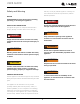
PINK PINK PUMP LIGHT TEST TERMINAL AMBIENT DOOR SWITCH COND TEMP BIN TEMP 10 6 16 9 J9 J10 AN 5 1 8 1 A NN TE LA PR OG G IN RA M FUSE 10 1 PURPLE OPEN CONTROL BOARD TO DI SP Y 42353_A WIRING DIAGRAM WATER VALVE WHITE (115V) DARK BLUE (220-240V) FAN GREEN W/ YELLOW (GROUND) (GROUND) GREEN W/YELLOW RELAY HOT GAS VALVE WHITE (115V) DARK BLUE (220-240V) NEUTRAL JUMPER PLUG WITHOUT P60 WASTE PUMP PINK (115V) DARK BLUE (230V) PINK (115V) DARK BLUE (230V) WHITE BL
USER GUIDE u-line.com SAFETY • INSTALLATION & INTEGRATION • OPERATING INSTRUCTIONS • MAINTENANCE • SERVICE Product Liability Field service technicians are authorized to make an initial assessment in the event of reported damages. If there are any questions about the process involved, the technician should call U-Line for further explanation. While inspecting for defects or installation issues, photos should be taken to document any damages or issues found.
USER GUIDE u-line.com SAFETY • INSTALLATION & INTEGRATION • OPERATING INSTRUCTIONS • MAINTENANCE • SERVICE Warranty Claims warranty status.
Parts 30 31 26 12 1 21 U-3045CLRINT-00B Item 10 35 22 11 17 32 3 18 37 15 33 34 25 Description U-Line P/N 1 Anti tip brackets w/screws 80-54012-00 2 Back panel 80-54083-00 3 Circulation pump 80-54064-00 4 Cleaner 80-54081-00 5 Compressor electricals only 80-54071-00 6 Compressor w/electricals 80-54069-00 7 Condenser 80-54079-00 8 Condenser fan 80-54065-00 9 Condenser fan blade 80-54066-00 10 Cover pump, black 80-54073-00 11 Cover w/ hook, black 80-54072-00 12
USER GUIDE u-line.com SAFETY • INSTALLATION & INTEGRATION • OPERATING INSTRUCTIONS • MAINTENANCE • SERVICE Ordering Replacement Parts If you have a purchasing account, please utilize our service website to order parts. Orders may also be placed by Fax or phone. See our contact information below: www.U-LineService.com (with service login) FAX Number: +1.414.354.5696 Phone Number: +1.800.779.2547 NOTICE Use only genuine U-Line replacement parts.
USER GUIDE u-line.
USER GUIDE u-line.com SAFETY • INSTALLATION & INTEGRATION • OPERATING INSTRUCTIONS • MAINTENANCE • SERVICE Compressor Specifications OVERLOAD PROTECTOR STARTING RELAY ! DANGER C S Electrocution can cause death or serious injury. R Burns from hot or cold surfaces can cause RELAY COVER serious injury. Take precautions when servicing CAPACITOR this unit. Electrical Relay and Overload Protector Disconnect the power source.
USER GUIDE u-line.com SAFETY • INSTALLATION & INTEGRATION • OPERATING INSTRUCTIONS • MAINTENANCE • SERVICE Troubleshooting - Extended Listed below are common refrigeration components with a SPECIFIC ERRORS AND ISSUES make. NOTE: Your product may not contain all the The technically advanced diagnostic capabilities of the components listed. brief description of the normal operating sounds they electronic controls utilized on the 3000 series units allows for easy and thorough trouble shooting.
USER GUIDE u-line.
USER GUIDE u-line.com SAFETY • INSTALLATION & INTEGRATION • OPERATING INSTRUCTIONS • MAINTENANCE • SERVICE MAIN CONTROL The main control board is very robust and is rarely the cause of system issues. It is important to fully diagnose the board for any suspected failures before attempting to remove the board for replacement or service. Follow the guidelines below to fully test and diagnose the main control.
USER GUIDE u-line.
USER GUIDE u-line.com SAFETY • INSTALLATION & INTEGRATION • OPERATING INSTRUCTIONS • MAINTENANCE • SERVICE SERVICE MENU The All Errors option keeps record of any system errors. In addition to a feature rich customer menu, the 3000 When an error occurs it is recorded to all errors. The series also offers a service menu with the ability to fine number next to the error indicates the number of recorded tune and monitor unit operation. instances. Errors in the log may not be currently active.
USER GUIDE u-line.com SAFETY • INSTALLATION & INTEGRATION • OPERATING INSTRUCTIONS • MAINTENANCE • SERVICE To access All Errors follow the steps below. 1. Press 2. Press 1. Use to select “All Errors”. 2. Press . 3. Press to select “Relay Status”. . and to scroll through available information. 3. Press and to scroll through available To exit the Relay Status simply press information. To clear the error log press press to exit. to select “Clear Errors” and to confirm.
USER GUIDE u-line.com SAFETY • INSTALLATION & INTEGRATION • OPERATING INSTRUCTIONS • MAINTENANCE • SERVICE Input Status Relay Toggle Up Up Select Select RETURN TO MENU RELAY TOGGLE MULL OFF COND OFF RETURN TO MENU INPUT STATUS DOOR OPEN IN2 OPEN Down Down Relay toggle is used to manually switch the state of each Input status displays the current state of each available relay to test for proper operation. In addition to the AC input. relays, DC switches may also be toggled.
USER GUIDE u-line.com SAFETY • INSTALLATION & INTEGRATION • OPERATING INSTRUCTIONS • MAINTENANCE • SERVICE To access Outputs To change offsets 1. Press 4. Press 2. Press 3. Press to select “Outputs”. . and to scroll through available , the selected thermistor will begin to flash. 5. Press or to modify offset value. 6. Press to confirm setting. information.
USER GUIDE u-line.
USER GUIDE u-line.com SAFETY • INSTALLATION & INTEGRATION • OPERATING INSTRUCTIONS • MAINTENANCE • SERVICE Re-Select Model allows the units model information to be Factory Default modified. Changing the units model completely Up reprograms available zones, relay assignments, DC output Select assignments etc. RETURN TO MENU FACTORY DEFAULT RESTORE? To access Re-Select Model # 1. Press Down Factory Default will restore all settings to their factory 2. Press default. to select “Re-Select Model”.
USER GUIDE u-line.com SAFETY • INSTALLATION & INTEGRATION • OPERATING INSTRUCTIONS • MAINTENANCE • SERVICE Fan Delay Showroom Mode Up Up Select Select RETURN TO MENU FAN DELAY FAN DELAY ON = 1 FAN DELAY OFF = 2 RETURN TO MENU SHOWROOM MODE OFF Down Down The Fan Delay menu option allows the modification of fan run times during and after a cooling cycle.
USER GUIDE u-line.com SAFETY • INSTALLATION & INTEGRATION • OPERATING INSTRUCTIONS • MAINTENANCE • SERVICE Thermistors The Ice Bin and Ambient Thermistors are both type 1 Thermistors are used for various temperature readings. the resistance can be verified. Place the thermistor in an Thermistors provide reliable temperature readings using a ice water bath, the resistance should read 16.5k OHMs resistance which varies based on surrounding +/-5% on your meter. thermistors.
USER GUIDE u-line.com SAFETY • INSTALLATION & INTEGRATION • OPERATING INSTRUCTIONS • MAINTENANCE • SERVICE The Condensor Line Out Thermistor is a type 2 thermistor. At 77° the resistance should read 10k OHMs +/-5%.
USER GUIDE u-line.com SAFETY • INSTALLATION & INTEGRATION • OPERATING INSTRUCTIONS • MAINTENANCE • SERVICE Defrost These models have no defrost options.
USER GUIDE u-line.com SAFETY • INSTALLATION & INTEGRATION • OPERATING INSTRUCTIONS • MAINTENANCE • SERVICE U-Line Corporation (U-Line) Limited Warranty One Year Limited Warranty For one year from the date of original purchase, this U-Line product warranty covers all parts and labor to repair or replace any part of the product that proves to be defective in materials or workmanship.