Installation Guide BI-95 Ice Maker www.U-LineService.com Phone (414) 354-0300 • FAX (414) 354-7905 Service & Parts Tech Lines Phone (800) 779-2547 • FAX (414) 354-5696 OnlineService@U-Line.
BI-95 Ice Maker Contents Exterior Cleaning . . . . . . . . . . . . . . . . . . . . . . . . . . . . . . Cut-Out Dimensions . . . . . . . . . . . . . . . . . . . . . . . . . . . Product Dimensions . . . . . . . . . . . . . . . . . . . . . . . . . . . . Door Swing/Clearances Information . . . . . . . . . . . . . . Reversing the Door. . . . . . . . . . . . . . . . . . . . . . . . . . . . . Other Site Requirements . . . . . . . . . . . . . . . . . . . . . . . . Custom 1/4" Thick Door Panel Insert . . . . . . .
BI-95 Ice Maker General Precautions 2 Inspect and Plan Use this appliance for its intended purpose only and follow these general precautions along with those listed throughout this guide: You have received a carton containing your BI-95 Ice Maker with a package inside containing a User Manual, a Product Registration Card and water connection parts. Complete and mail the Product Registration Card or register online at www.U-LineService.com.
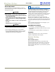
BI-95 Ice Maker Product Dimensions 3 Prepare Site 17" Including Handle Your U-Line product has been designed for either freestanding or built-in installation. When built-in, your unit does not require additional air space for top, sides or rear. However, the front grille must NOT be obstructed and clearance is required for water and electrical connections in the rear. Note: Unit can NOT be installed behind a closed cabinet door.
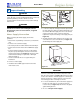
BI-95 Ice Maker Reversing the Door 5. Relocate plastic spacer/ bushing on bottom of door to opposite side, and place door on bottom hinge pin. See Figure 8. Clean out bushing hole in door bottom with a screwdriver if necessary. All units may be left- or right-hand opening. Note: The grille should not yet be installed. If it has been installed, remove it for door reversing. See Page 10. To reverse the door: 1. Remove top hinge from cabinet (three screws). See Figure 4. Hold door to keep it from falling.
BI-95 Ice Maker 10. Fasten upper hinge to unit (three screws). Partially tighten screws. See Figure 11. 4 Prepare and Install Door Panel Units will accept a Custom 1/4" Thick Insert to harmonize with or accent the surrounding decor. 11. Adjust door to assure proper seal. Tighten upper and lower hinge screws securely. 12. Replace three plastic plugs removed in Step 8 into holes on top of unit. Replace screws in holes in bottom of unit on opposite side.
BI-95 Ice Maker 5 Adjust Door Checking Door Alignment The unit’s door is aligned at the factory before shipment. However, its alignment could have been disturbed during shipment or during door panel installation. IMPORTANT Figure 12 Properly aligned, the door's gasket should be firmly in contact with the cabinet all the way around the door (no gaps). Figure 13 1. Carefully examine the door's gasket to assure that it is firmly in contact with the cabinet. 2.
BI-95 Ice Maker 6 Prepare Plumbing CAUTION Plumbing installation must observe all state and local codes. All water connections MUST BE made by a licensed/ qualified plumbing contractor. Failure to follow recommendations and instructions may result in damage and/or harm. Water Line WARNING Figure 16 To prevent accidental electrocution, make certain that the floor surfaces surrounding the unit are dry whenever power is removed from, or applied to, the unit. Figure 17 2.
BI-95 Ice Maker 7 Prepare Power Supply 8 Level the Unit Electrical Specifications Leveling Information CAUTION IMPORTANT It is extremely important that the unit sits on a level surface, as it does not have feet levelers. If it is not level, the ice mold will not fill evenly. Electrical installation must observe all state and local codes. This unit requires connection to a grounded (threeprong), polarized receptacle that has been placed by a qualified electrician.
BI-95 Ice Maker 9 Install the Unit Installation of the BI-95 1. Open the water supply valve in the main water source. Grille 2. Plug in the power cord. 3. Gently push the unit into position. Be careful not to kink the water supply line or entangle the electrical cord. Hook-Hinge Unit Base Front Lip 4. Re-check the leveling, from front to back and side to side. Make any necessary adjustments. The unit’s top surface should be approximately 1/8" below the countertop. 4. Insert the screw.
BI-95 Ice Maker Start-Up Troubleshooting 10 Start-Up for the First Time Initial Start-Up Q: Problem The on/off switch is located behind the front grille. A small opening in the top of the grille is provided to access the switch. Ensure that the switch is turned on. A: Solution Unit does not appear to turn on when plugged in. Make sure outlet has power (circuit breaker has not tripped). Make sure the on/off switch is turned on. No setting adjustments should be necessary at this time.
Who to Call Service Information If the need for service arises, contact the dealer from whom the unit was purchased. State the Model Number and Serial Number and explain the problem. The Model and Serial Number plate is located inside unit at upper right hand corner. If you need to locate a service company, you can go online at www.U-LineService.com and search for a service company by zip code.