USER GUIDE SAFETY • INSTALLATION & INTEGRATION • OPERATING INSTRUCTIONS • MAINTENANCE • SERVICE RIGHT PRODUCT. RIGHT PLACE. RIGHT TEMPERATURE. SINCE 1962.
USER GUIDE u-line.
USER GUIDE u-line.com WELCOME TO U-LINE Congratulations on your U-Line purchase. Your product comes from a company with over five decades and three generations of premium modular ice making, refrigeration, and wine preservation experience. U-Line continues to be the American leader, delivering versatility and flexibility for multiple applications including residential, light commercial, outdoor and marine use.
USER GUIDE u-line.com SAFETY • INSTALLATION & INTEGRATION • OPERATING INSTRUCTIONS • MAINTENANCE • SERVICE Safety and Warning NOTICE Please read all instructions before installing, operating, or servicing the appliance.
USER GUIDE u-line.com SAFETY • INSTALLATION & INTEGRATION • OPERATING INSTRUCTIONS • MAINTENANCE • SERVICE Disposal and Recycling ! DANGER RISK OF CHILD ENTRAPMENT. Before you throw away your old refrigerator or freezer, take off the doors and leave shelves in place so children may not easily climb inside.
USER GUIDE u-line.com SAFETY • INSTALLATION & INTEGRATION • OPERATING INSTRUCTIONS • MAINTENANCE • SERVICE Environmental Requirements This unit is designed to operate between 50°F (10°C) and 100°F (37°C). High ambient temperatures (100°F [37°C] or higher) may reduce the unit’s ability to reach low temperatures. For best performance, keep the unit out of direct sunlight and away from heat generating equipment.
USER GUIDE u-line.com SAFETY • INSTALLATION & INTEGRATION • OPERATING INSTRUCTIONS • MAINTENANCE • SERVICE Electrical ! WARNING SHOCK HAZARD — Electrical Grounding Required. Never attempt to repair or perform maintenance on the unit until the electricity has been disconnected. Never remove the round grounding prong from the plug and never use a two-prong grounding adapter.
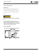
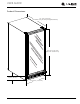
USER GUIDE u-line.com SAFETY • INSTALLATION & INTEGRATION • OPERATING INSTRUCTIONS • MAINTENANCE • SERVICE Cutout Dimensions PREPARE SITE Your U-Line product has been designed for either freestanding or built-in installation. When built-in, your unit does not require additional air space for top, sides, or rear. However, the front grille must NOT be obstructed, and clearance is required for an electrical connection in the rear. ! CAUTION Unit can NOT be installed behind a closed cabinet door.
USER GUIDE u-line.
USER GUIDE u-line.com SAFETY • INSTALLATION & INTEGRATION • OPERATING INSTRUCTIONS • MAINTENANCE • SERVICE Side-by-Side Installation Two units may be installed side-by-side. Cutout width for a side-by-side installation is the cutout dimension of a single unit times two. No trim kit is required. However, 1/4" (6 mm) of space 3. Place bracket over holes and attach to unit with two screws removed in step 2 using a T-25 Torx driver. Tighten screws fully. 4. Gently push units into position.
USER GUIDE u-line.com SAFETY • INSTALLATION & INTEGRATION • OPERATING INSTRUCTIONS • MAINTENANCE • SERVICE Water Hookup PREPARE PLUMBING ! CAUTION Please use the braided stainless steel water supply line Do not use any plastic water supply line. The line which comes attached. The water line is fitted with a is under pressure at all times. Plastic may crack standard 1/4" (6.35 mm) compression fitting. or rupture with age and cause damage to your home.
USER GUIDE u-line.com SAFETY • INSTALLATION & INTEGRATION • OPERATING INSTRUCTIONS • MAINTENANCE • SERVICE 4. Turn on water and check for leaks. 5. Route water supply line in cable clamp and secure with screw.
USER GUIDE u-line.com SAFETY • INSTALLATION & INTEGRATION • OPERATING INSTRUCTIONS • MAINTENANCE • SERVICE Drain GRAVITY DRAIN Models ending in (-00A, -01A) will not be equipped with factory installed drain pump. Normal Proper Drain Models ending in (-40A, -41A) will have the factory installed drain pump.
USER GUIDE u-line.com SAFETY • INSTALLATION & INTEGRATION • OPERATING INSTRUCTIONS • MAINTENANCE • SERVICE FACTORY INSTALLED DRAIN PUMP If your drain line will run up to a stand pipe, disposal or Y-Branch Tailpiece P60 Pump Required Air Gap (Optional Hook-Up) spigot assembly, or does not otherwise meet the requirements for a gravity drain, you may have ordered a pre-installed U-Line P60 drain pump. Waste If you need to install a P60 drain pump into your unit, (see 6KXW 2ɞ Valve “Drain Pump”).
USER GUIDE u-line.com SAFETY • INSTALLATION & INTEGRATION • OPERATING INSTRUCTIONS • MAINTENANCE • SERVICE Drain Pump NOTICE INCLUDED IN KIT: 1. 1x S-shaped Drain Tube (Not used) 1 PLEASE READ this instruction completely before attempting to install or operate the unit. Improper hook-up can result in substantial property damage! If you are unsure of your ability to safely connect the drain pump to the 2. 1x Straight Drain Tube 2 3. 1x Vent Tube 3 unit, consult a licensed plumber for assistance.
USER GUIDE u-line.com SAFETY • INSTALLATION & INTEGRATION • OPERATING INSTRUCTIONS • MAINTENANCE • SERVICE Note: Slide clamp on hose end before installing hose. Do not 8 tighten clamp until pump and hoses have been installed. 6. Install the 3 hoses and hose clamps to the pump assembly Wiring Plug as shown below. Do not tighten Ground Terminal Discharge Tube Connector clamps at this time.
USER GUIDE u-line.com SAFETY • INSTALLATION & INTEGRATION • OPERATING INSTRUCTIONS • MAINTENANCE • SERVICE ! WARNING The back panel serves as a guard. Do not put your hands inside the ice machine cabinet or attempt to touch any components except the discharge tube during testing. ! CAUTION Failure to properly secure the vent tube will result in water damage to the unit and surrounding areas. Do not allow vent tube to kink, bend or be obstructed in any way.
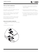
USER GUIDE u-line.com SAFETY • INSTALLATION & INTEGRATION • OPERATING INSTRUCTIONS • MAINTENANCE • SERVICE Anti-Tip Bracket 1. Slide unit out so screws on top of unit are easily accessible. 2. Remove the two screws from the opposite side of the hinge assembly using a T-25 Torx driver (see below). NOTE: 1224 models shown with four screw. 1215 models only have three screws, but same screws are used in both applications. 3.
USER GUIDE u-line.com SAFETY • INSTALLATION & INTEGRATION • OPERATING INSTRUCTIONS • MAINTENANCE • SERVICE General Installation INSTALLATION 1. Plug in the power/electrical cord. LEVELING INFORMATION 1. Use a level to 2. Gently push the unit into position. Be careful not to confirm the unit is entangle the cord or water and drain lines. level. Level should be placed along top 3. Re-check the leveling, from front to back and side to edge and side edge side. Make any necessary adjustments.
USER GUIDE u-line.com SAFETY • INSTALLATION & INTEGRATION • OPERATING INSTRUCTIONS • MAINTENANCE • SERVICE Integrated Panel Dimensions INTEGRATED PANEL Integrated Panel Dimensions BACK SURFACE MUST HAVE AMPLE FLAT SURFACE TO MOUNT OVERLAY PANEL FLAT AND WITHOUT 3/4" INTERFERENCE (20 mm) NOTICE Due to differences in surrounding cabinetry the panel may not perfectly align with door.
USER GUIDE u-line.com SAFETY • INSTALLATION & INTEGRATION • OPERATING INSTRUCTIONS • MAINTENANCE • SERVICE Integrated Panel Installation 1. Fully open door/drawer. 6. Secure integrated panel to door/drawer Bar Clamp using clamps. A robust tape may also be used. U-Line 2. Starting at corner, pull recommends the use gasket away from door/ of bar clamps to drawer. Door/Drawer secure the panel to the door/drawer. If 3. Continue to pull gasket using tape, be free from gasket channel.
USER GUIDE u-line.com SAFETY • INSTALLATION & INTEGRATION • OPERATING INSTRUCTIONS • MAINTENANCE • SERVICE 11.Remove clamps from door/drawer. NOTICE If panel requires additional adjustment after removing clamps, slightly loosen each screw and adjust panel as necessary. Tighten screws upon completion. 12.Starting at the corners, re-install the gasket into the gasket channel in the frame. Make sure the gasket is fully seated. This may take some force.
USER GUIDE u-line.com SAFETY • INSTALLATION & INTEGRATION • OPERATING INSTRUCTIONS • MAINTENANCE • SERVICE Grille - Plinth Installation REMOVING AND INSTALLING GRILLE ! WARNING Disconnect electric power to the unit before removing the grille. ! WARNING DO NOT touch the condenser fins (4). The condenser fins are SHARP and can be easily damaged. Removing the grille 1. Disconnect power to the unit. 2. Loosen the two screws (1). 3. Remove grille (2) and grille cap (3) from unit.
USER GUIDE u-line.com SAFETY • INSTALLATION & INTEGRATION • OPERATING INSTRUCTIONS • MAINTENANCE • SERVICE Door Swing Wall Wall 1/4" Min. (6 mm) 90 Door Swing 2-1/8" Min. (54 mm) 90 Door Swing Units have a zero clearance for the door to open 90°, when installed adjacent to cabinets. Stainless Steel and black and white models require 2-1/8" (54 mm) door clearance to accommodate the handle if installed next to a wall. Integrated models require 1/4" (6 mm) clearance if installed next to a wall.
USER GUIDE u-line.com SAFETY • INSTALLATION & INTEGRATION • OPERATING INSTRUCTIONS • MAINTENANCE • SERVICE Door Stop 3. On 24" models, a second pin is included for the bottom hinge. Repeat steps above for second hinge. Your U-Line unit was shipped to you with the optional 90° pin(s). (Models that are 15" wide include 1 pin. Models that are 24" wide include 2 pins.) The unit’s door will open NOTE: Threaded pin will be inserted from the bottom. freely without a fixed opening angle limitation.
USER GUIDE u-line.com SAFETY • INSTALLATION & INTEGRATION • OPERATING INSTRUCTIONS • MAINTENANCE • SERVICE Door Adjustments DOOR ALIGNMENT AND ADJUSTMENT Align and adjust the door if it is not level or is not sealing properly. If the door is not sealed, the unit may not cool properly, or excessive frost may form in the interior. NOTICE Properly aligned, the door’s gasket should be firmly in contact with the cabinet all the way around the door (no gaps).
USER GUIDE u-line.com SAFETY • INSTALLATION & INTEGRATION • OPERATING INSTRUCTIONS • MAINTENANCE • SERVICE Remove bottom hinge: Prepare door for reinstallation: 1. Remove bottom hinge from cabinet. 1. Rotate door 180° to reverse. 2. Remove gasket center strip and apply in-line with new opening (approximately 2" lower). Install top hinge and door: 1. Use alternate hinge supplied with unit and reinstall the screws. 2. Remove corresponding screws on opposite side of cabinet.
USER GUIDE u-line.com SAFETY • INSTALLATION & INTEGRATION • OPERATING INSTRUCTIONS • MAINTENANCE • SERVICE First Use All U-Line controls are preset at the factory. Initial startup requires no adjustments. NOTICE U-Line recommends discarding the ice produced during the first two to three hours of operation to avoid possible dirt or scale that may dislodge from the water line. When plugged in, the unit will begin operating under the factory default settings.
USER GUIDE u-line.com SAFETY • INSTALLATION & INTEGRATION • OPERATING INSTRUCTIONS • MAINTENANCE • SERVICE Control Operation Up Down Alert Light Power Clean LED CONTROL FUNCTION GUIDE FUNCTION COMMAND DISPLAY/OPTIONS ON/OFF Press Unit will immediately turn ON or OFF.
USER GUIDE u-line.com SAFETY • INSTALLATION & INTEGRATION • OPERATING INSTRUCTIONS • MAINTENANCE • SERVICE Ice Cube Types ICE CUBE THICKNESS ADJUSTMENT 1/16" TO 1/8" (1.6 mm to 3.2 mm) ICE BRIDGE 1/4" TO 1/2" (6.4 mm to 12.7 mm) DIMPLE Interval - As Required NOTICE Ice thickness adjustment should only be made one increment at a time. Allow ice maker production to stabilize for 24 hours before rechecking ice thickness. 1.
USER GUIDE u-line.com SAFETY • INSTALLATION & INTEGRATION • OPERATING INSTRUCTIONS • MAINTENANCE • SERVICE L Sabbath Mode 1 2 3 4 5 6 Up Select Down U-Line Clear Ice Machine models are Star-K certified and can be used during the Sabbath. View a full list of Star-K certified U-Line units at www.star-k.org. To prepare the unit for the Sabbath: 1. Press and hold the until the unit turns off. 2.
USER GUIDE u-line.com SAFETY • INSTALLATION & INTEGRATION • OPERATING INSTRUCTIONS • MAINTENANCE • SERVICE Airflow and Product Loading NOTICE The unit requires proper airflow to perform at its highest efficiency. Do not block the front grille at any time, or the unit will not perform as expected. Do not install the unit behind a door.
USER GUIDE u-line.com SAFETY • INSTALLATION & INTEGRATION • OPERATING INSTRUCTIONS • MAINTENANCE • SERVICE Cleaning Using abrasive pads such as ScotchBrite™ will EXTERIOR CLEANING become blurred. cause the graining in the stainless steel to Vinyl Clad (Black or White) Models Clean surfaces with a mild detergent and warm water Rust not cleaned up promptly can penetrate the solution. Do not use solvent-based or abrasive cleaners.
USER GUIDE u-line.com SAFETY • INSTALLATION & INTEGRATION • OPERATING INSTRUCTIONS • MAINTENANCE • SERVICE 5. Re-install the standpipe into the water trough. NOTICE Use only U-Line Ice Machine Cleaner (Part No. 37050, available from your dealer or direct from your local parts distributor. To locate a parts distributor near you, visit www.u-line.com. It is a violation of federal law to use this solution in a Evaporator manner inconsistent with its labeling.
USER GUIDE u-line.com SAFETY • INSTALLATION & INTEGRATION • OPERATING INSTRUCTIONS • MAINTENANCE • SERVICE 9. When water begins flowing over the evaporator (approximately 3 minutes), pour 1 packet of CLR cleaner into the water trough. The cleaning process will last approximately 45 minutes. 10.Dilute 1 tablespoon bleach in 1 gallon of warm water. Apply this solution to the entire inside of the storage area. Then rinse thoroughly with water.
USER GUIDE u-line.com SAFETY • INSTALLATION & INTEGRATION • OPERATING INSTRUCTIONS • MAINTENANCE • SERVICE Cleaning Condenser INTERVAL - EVERY SIX MONTHS To maintain operational efficiency, keep the front grille free of dust and lint, and clean the condenser when necessary. Depending on environmental conditions, more or less frequent cleaning may be necessary. ! WARNING Disconnect electric power to the unit before cleaning the condenser. NOTICE DO NOT use any type of cleaner on the condenser unit.
USER GUIDE u-line.com SAFETY • INSTALLATION & INTEGRATION • OPERATING INSTRUCTIONS • MAINTENANCE • SERVICE Extended Non-Use VACATION/HOLIDAY, PROLONGED SHUTDOWN For questions regarding winterization, please The following steps are recommended for periods of call U-Line at +1.800.779.2547. extended non-use: 1. Remove all consumable content from the unit. 2. Disconnect the power cord from its outlet/socket and leave it disconnected until the unit is returned to service.
USER GUIDE u-line.com SAFETY • INSTALLATION & INTEGRATION • OPERATING INSTRUCTIONS • MAINTENANCE • SERVICE Accessories 23054-01 37050 80-51002-00 Accessories - Clear Ice Accessories - Clear Ice Accessories - Stainless Steel Maker Refresh Kit Machine Cleaner - 1 Box of PRO Style Door Handle, US$98.99 6 packets 1-1/4" in diameter US$39.00 US$49.
USER GUIDE u-line.com SAFETY • INSTALLATION & INTEGRATION • OPERATING INSTRUCTIONS • MAINTENANCE • SERVICE Troubleshooting • Evaporator: Refrigerant flowing through an evaporator may sound like boiling liquid. BEFORE CALLING FOR SERVICE If you think your U-Line product is malfunctioning, read the CONTROL OPERATION section to clearly understand the function of the control.
USER GUIDE u-line.com SAFETY • INSTALLATION & INTEGRATION • OPERATING INSTRUCTIONS • MAINTENANCE • SERVICE Warranty unit is completed and mailed back or electronically U-LINE CORPORATION LIMITED WARRANTY apply to cosmetic damages. A proof of purchase may 1. U-Line Corporation (“U-Line”) warrants each U-Line be required. submitted to U-Line.
USER GUIDE u-line.com SAFETY • INSTALLATION & INTEGRATION • OPERATING INSTRUCTIONS • MAINTENANCE • SERVICE 7. If a product defect is discovered during the applicable warranty period, you must promptly notify either U-Line at 8900 N. 55th Street, Milwaukee, Wisconsin 53223 USA or at +1.800.779.2547 or the dealer from whom you purchased the product. In no event shall such notification be received later than 30 days after the expiration of the applicable warranty period.