™ Installation Guide CLR2060 — Clear Ice Maker www.U-LineService.com Phone (414) 354-0300 • FAX (414) 354-7905 Service & Parts Tech Lines Phone (800) 779-2547 • FAX (414) 354-5696 OnlineService@U-Line.
™ CLR2060 — Clear Ice Maker Contents Cut-Out Dimensions . . . . . . . . . . . . . . . . . . . . . . . . . . . Product Dimensions . . . . . . . . . . . . . . . . . . . . . . . . . . . . Door Swing/Clearances Information . . . . . . . . . . . . . . Reversing the Door. . . . . . . . . . . . . . . . . . . . . . . . . . . . . Other Site Requirements . . . . . . . . . . . . . . . . . . . . . . . . Side-By-Side Installation Instructions . . . . . . . . . . . . . . Custom 1/4'' Door Panel Insert . . . . . . . . .
™ CLR2060 — Clear Ice Maker General Precautions 2 Inspect and Plan Use this appliance for its intended purpose only and follow these general precautions along with those listed throughout this guide: You have received a carton containing your CLR2060 Clear Ice Maker with a package inside containing a User Manual, a Product Registration Card and water connection parts. Complete and mail the Product Registration Card or register online at www.U-LineService.com.
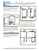
™ CLR2060 — Clear Ice Maker Product Dimensions 3 Prepare Site 24" Including Handle Your U-Line product has been designed for either freestanding or built-in installation. When built-in, your unit does not require additional air space for top, sides or rear. However, the front grille must NOT be obstructed and clearance is required for water, drain and electrical connections in the rear. 26-1/8" Including Handle Note: Unit can NOT be installed behind a closed cabinet door.
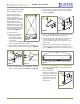
™ CLR2060 — Clear Ice Maker Reversing the Door 4. Remove the two door closer inserts from the existing bottom hinge and install as shown on the new bottom hinge (see Figure 8). (Black and White Units Only) All U-Line units (except Stainless Steel models) may be left- or right-hand opening. The door opening is easily reversed by moving the hinge hardware to the opposite side.
™ CLR2060 — Clear Ice Maker Other Site Requirements Side-By-Side Installation Instructions Power Supply For a complete refreshment center, install your CLR2060 Clear Ice Maker beside a U-line Refrigerator, Combo, or Wine Captain Model (see Figure 11 for typical cut-out). Note that each Side-By-Side Installation will be different. The unit requires a grounded and polarized 115 VAC, 60 Hz, 15A circuit (normal household current). See Electrical Specifications on Page 16.
™ CLR2060 — Clear Ice Maker 4 Prepare and Install Door Panel (Black and White Units Only) Two types of custom door panels can be installed on your Black or White unit to harmonize with or accent the surrounding décor: a Custom 1/4" Insert or a Full Overlay. If no custom door panel is used, go on to 5 Adjust Door. Custom 1/4'' Door Panel Insert Door Panel Preparation Figure 12 A custom door panel can be inserted into the doorframe.
™ CLR2060 — Clear Ice Maker Full Overlay Door Panel 13/32" 0.177" Dia. (#16 Drill) x 11/16" Deep Door Panel Preparation 13/32" 3/8" A full overlay door panel completely covers the doorframe and handle to give a built-in appearance. See your U-Line dealer for the optional Full Overlay Door Panel Kit (P/N U-OL2015B — Black or P/N U-OL2015W — White). Appropriate hardware, Modified Handle, Replacement Hinges and a copy of these instructions will be included in the kit. 3/8" Door Bottom: 5/16" Dia.
™ CLR2060 — Clear Ice Maker 4. Drill hole for upper door hinge (top of panel) (see Figure 16, Top View). 4. Remove the top handle and discard. (This handle will be replaced with the Modified Handle included in the Full Overlay Door Panel Kit.) 0.177" diameter (#16 drill) x 11/16" deep 5. Remove the two screws located on both sides of the lower handle. Remove the handle. 5. Drill hole for lower door hinge (see Figure 16, Bottom View). 6.
™ CLR2060 — Clear Ice Maker Typical Wood Panel Tape Back of Wood Panel Removed Door Panel Door Panel Top Pivot Plate #10 x 5/8" Round Head Screw Six Required Plastic Spacer Six Required Side of Wood Panel Bottom of Wood Panel 5/16" Bottom Figure 22 3/8" Both Sides 5. Remove the existing bottom pivot plate and replace with the Full Overlay pivot plate (see Figure 23).
™ CLR2060 — Clear Ice Maker 5 Adjust Door Pivot Post Wood Panel Top Hinge Plate (5/8" Longer than Existing Top Hinge Plate) Checking Door Alignment The unit’s door is aligned at the factory before shipment. However, its alignment could have been disturbed during shipment or during door panel installation. #8-32 x 1/2" Flat Head Screw Three Places IMPORTANT Top Pivot Plate Properly aligned, the door should be 1/8" below the top of the unit’s cabinet, NOT flush with the top (see Figure 26).
™ CLR2060 — Clear Ice Maker 6 Prepare Plumbing CAUTION Slotted Mounting Holes Plumbing installation must observe all state and local codes. All water and drain connections MUST BE made by a licensed/qualified plumbing contractor. Failure to follow recommendations and instructions may result in damage and/or harm. Notch Drain Connection Raise Outside Door Edge Lower Outside Door Edge IMPORTANT Figure 28 Drain can NOT be located directly below unit.
™ CLR2060 — Clear Ice Maker Gravity Drain Disposal Assembly Air Gap (Optional Hook-Up) Waste Shut-Off Valve Waste Cold Water Hot Water Hot Water Cold Water Shut-Off Valve Waste Figure 33 Figure 31 If using a Gravity Drain: Spigot Assembly Air Gap (Optional Hook-Up) 1. Attach the 5/8-inch ID drain connection on the back of the unit to a 5/8-inch OD rigid tube, using a worm clamp. 2. Attach the other end of the rigid tube to your 5/8-inch ID drain line with a worm clamp. Waste 3.
CLR2060 — Clear Ice Maker To check and test hose connections: ™ 5. Place a suitable container beneath the pump’s discharge tube. (The bucket must be able to hold a minimum of one gallon.) 1. Make certain the unit is not plugged into an electrical outlet. 6. Plug the ice maker power cord into a properly grounded, polarized electrical outlet. 2. Carefully push the power cord grommet through the hole in the back panel (see Figure 35). 7.
™ CLR2060 — Clear Ice Maker 3. Carefully bend the water supply line into position and connect the line to the solenoid valve (see Figure 39). Avoid kinking the water supply line. CAUTION In the event of a power outage, restricted drain or pump failure, the failure to use the U-Line P60 drain pump or a pump with the above listed specifications, could result in substantial water leakage and pooling with severe and costly water damage and related consequential damages and harm.
™ CLR2060 — Clear Ice Maker 7 Prepare Power Supply 8 Level the Unit Electrical Specifications Leveling Information CAUTION IMPORTANT It is extremely important that the unit is level. If it is not level, the ice mold will not fill evenly. Electrical installation must observe all state and local codes. This unit requires connection to a grounded (threeprong), polarized receptacle that has been placed by a qualified electrician.
™ CLR2060 — Clear Ice Maker 2. If the ice maker is not level, adjust the feet on the corners of the unit as necessary (see Figure 44). 9 Install the Unit Installation of the CLR2060 1. Open the water supply valve in the main water source. 2. Plug in the power cord. 3. Gently push the unit into position. Be careful not to kink the drain or water supply line or entangle the electrical cord. Turn Foot to Adjust 4. Re-check the leveling, from front to back and side to side. Make any necessary adjustments.
™ CLR2060 — Clear Ice Maker Installation Troubleshooting 10 Start-Up for the First Time Q: Problem Initial Start-Up Water is leaking under the unit. Once installation and leveling is complete, the unit is ready for initial start-up and operation. The cycle selector switch is located in the front grille (see Figure 45). A: Solution O F F I C E C L N O F F I C E A water leak under the unit is most likely caused by a bad connection in the water supply line.
™ CLR2060 — Clear Ice Maker Start-Up Troubleshooting 4. Watch the water flow over the evaporator assembly (ice cube tray) to familiarize yourself with the operation. Upon initial start-up, water flow over the evaporator may be uneven. This may cause uneven sized cubes or water spilling into the ice storage bin. This is a normal situation and will correct itself within the first 24 hours of operation. Q: Problem Unit does not appear to turn on when switch is set to ICE. A: Solution 5.
™ Who to Call Service Information If the need for service arises, contact the dealer from whom the unit was purchased. State the Model Number and Serial Number and explain the problem. The Model and Serial Number plate is located inside unit at upper right hand corner. If you need to locate a service company, you can go online at www.U-LineService.com and search for a service company by zip code.