™ Installation Guide CLRCO2075 — Clear Ice Maker/Refrigerator www.U-LineService.com Phone (414) 354-0300 • FAX (414) 354-7905 Service & Parts Tech Lines Phone (800) 779-2547 • FAX (414) 354-5696 OnlineService@U-Line.
™ CLRCO2075 — Clear Ice Maker/Refrigerator Contents Exterior Cleaning . . . . . . . . . . . . . . . . . . . . . . . . . . . . . . Cut-Out Dimensions . . . . . . . . . . . . . . . . . . . . . . . . . . . Product Dimensions . . . . . . . . . . . . . . . . . . . . . . . . . . . . Door Swing/Clearances Information . . . . . . . . . . . . . . Reversing the Door. . . . . . . . . . . . . . . . . . . . . . . . . . . . . Other Site Requirements . . . . . . . . . . . . . . . . . . . . . . . .
™ CLRCO2075 — Clear Ice Maker/Refrigerator General Precautions 2 Inspect and Plan Use this appliance for its intended purpose only and follow these general precautions along with those listed throughout this guide: You have received a carton containing your CLRCO2075 Clear Ice Maker/Refrigerator with a package inside containing a User Manual, a Product Registration Card and water connection parts. Complete and mail the Product Registration Card or register online at www.U-LineService.com.
™ CLRCO2075 — Clear Ice Maker/Refrigerator After all the protective coating has been removed from the unit/door, clean all Stainless Steel surfaces with Claire Stainless Steel Polish and Cleaner or comparable product or a mild detergent and warm water solution and soft cloth. Do NOT use abrasive cleaning agents.
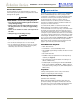
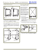
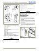
™ CLRCO2075 — Clear Ice Maker/Refrigerator Product Dimensions Reversing the Door (Black and White Units Only) 26-1/8" Including Handle 24" Including Handle 34-1/8" 34-1/8" 23-15/16" Black and White All U-Line units (except Stainless Steel models) may be left- or right-hand opening. The door opening is easily reversed by moving the hinge hardware to the opposite side.
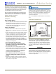
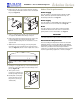
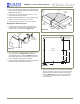
™ CLRCO2075 — Clear Ice Maker/Refrigerator Other Site Requirements 4. Remove the two door closer inserts from the existing bottom hinge and install as shown on the new bottom hinge (see Figure 8). Power Supply The unit requires a grounded and polarized 115 VAC, 60 Hz, 15A circuit (normal household current). See Electrical Specifications on Page 16. Hinge Screw Pin Water Supply Door Closer Inserts The unit requires a 1/4-inch OD water supply line and a shut-off valve. For more information see Page 15.
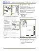
™ CLRCO2075 — Clear Ice Maker/Refrigerator Side-By-Side Installation Instructions 4 Prepare and Install Door Panel (Black and White Units Only) For a complete refreshment center, install your CLRCO2075 Clear Ice Maker/Refrigerator beside a U-Line Drawer or Wine Captain Model (see Figure 11 for typical cut-out). Note that each Side-By-Side Installation will be different.
™ CLRCO2075 — Clear Ice Maker/Refrigerator Full Overlay Door Panel Door Panel Preparation A full overlay door panel completely covers the doorframe and handle to give a built-in appearance. See your U-Line dealer for the optional Full Overlay Door Panel Kit (P/N U-OL2075B — Black or P/N U-OL2075W — White). Appropriate hardware, Modified Handle, Replacement Hinges and a copy of these instructions will be included in the kit. Figure 12 1. Cut the overlay to the following dimensions (see Figure 15).
™ 13/32" CLRCO2075 — Clear Ice Maker/Refrigerator 0.177" Dia. (#16 Drill) x 11/16" Deep 4. Drill hole for upper door hinge (top of panel) (see Figure 16, Top View). 13/32" 0.177" diameter (#16 drill) x 11/16" deep 3/8" 3/8" 5. Drill hole for lower door hinge (see Figure 16, Bottom View). Door Bottom: 5/16" Dia.
™ CLRCO2075 — Clear Ice Maker/Refrigerator 5. Remove the top handle and discard. (This handle will be replaced with the Modified Handle included in the Full Overlay Door Panel Kit.) Tape Back of Wood Panel Removed Door Panel 6. Remove the two screws located on both sides of the lower handle. Remove the handle. 7. Attach the Modified Handle to the lower handle using the three screws removed in Step 4. Set aside. 8. Slide the existing door panel out of the doorframe.
™ CLRCO2075 — Clear Ice Maker/Refrigerator Typical Wood Panel Door Panel Pivot Post Wood Panel Top Hinge Plate (5/8" Longer than Existing Top Hinge Plate) Top Pivot Plate #10 x 5/8" Round Head Screw Seven Required #8-32 x 1/2" Flat Head Screw Three Places Plastic Spacer Seven Required Top Pivot Plate Figure 22 Door Panel 5. Remove the existing bottom pivot plate and replace with the Full Overlay pivot plate (see Figure 23). Figure 24 3.
™ CLRCO2075 — Clear Ice Maker/Refrigerator 5 Adjust Door Checking Door Alignment The unit’s door is aligned at the factory before shipment. However, its alignment could have been disturbed during shipment or during door panel installation. Slotted Mounting Holes Notch IMPORTANT Properly aligned, the door should be 1/8" below the top of the unit’s cabinet, NOT flush with the top (see Figure 26). Raise Outside Door Edge Lower Outside Door Edge Figure 28 1/8" 3. See Figure 28.
™ CLRCO2075 — Clear Ice Maker/Refrigerator Gravity Drain 6 Prepare Plumbing CAUTION Plumbing installation must observe all state and local codes. All water and drain connections MUST BE made by a licensed/qualified plumbing contractor. Failure to follow recommendations and instructions may result in damage and/or harm. Waste Shut-Off Valve Cold Water Hot Water Drain Connection IMPORTANT Drain can NOT be located directly below unit. Unit has a solid base that will not allow unit to drain below itself.
™ CLRCO2075 — Clear Ice Maker/Refrigerator To check and test hose connections: Disposal Assembly 1. Make certain the unit is not plugged into an electrical outlet. Air Gap (Optional Hook-Up) 2. Carefully push the power cord grommet through the hole in the back panel (see Figure 35). Waste Hot Water Screws Back Panel Cold Water Shut-Off Valve Figure 33 Spigot Assembly Air Gap (Optional Hook-Up) Grommet Drain Fitting Power Cord Water Connection Figure 35 Waste 3.
™ CLRCO2075 — Clear Ice Maker/Refrigerator 5. Place a suitable container beneath the pump’s discharge tube. (The bucket must be able to hold a minimum of one gallon.) CAUTION In the event of a power outage, restricted drain or pump failure, the failure to use the U-Line P60 drain pump or a pump with the above listed specifications, could result in substantial water leakage and pooling with severe and costly water damage and related consequential damages and harm. 6.
™ CLRCO2075 — Clear Ice Maker/Refrigerator 3. Carefully bend the water supply line into position and connect the line to the solenoid valve (see Figure 39). Avoid kinking the water supply line. 7 Prepare Power Supply Electrical Specifications CAUTION Electrical installation must observe all state and local codes. This unit requires connection to a grounded (threeprong), polarized receptacle that has been placed by a qualified electrician.
™ CLRCO2075 — Clear Ice Maker/Refrigerator 2. If the ice maker is not level, adjust the feet on the corners of the unit as necessary (see Figure 43). 8 Level the Unit Leveling Information IMPORTANT It is extremely important that the unit is level. If it is not level, the ice mold will not fill evenly. A unit that is not level can cause a reduction in ice rate, uneven sized cubes or water spilling into the storage area, which will cause the ice in the bin to melt prematurely (see Figure 41).
™ CLRCO2075 — Clear Ice Maker/Refrigerator Door Shelves 9 Install the Unit 1. First pull shelf up at a 45° angle, then straight out (see Figure 45). Installation of the CLRCO2075 1. Open the water supply valve in the main water source. Notch 2. Choose new location and line up on bosses. First push straight in, then down at a 45° angle. 2. Make sure the cycle selector switch is in the OFF (middle) position (see Figure 46).
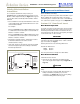
™ CLRCO2075 — Clear Ice Maker/Refrigerator Temperature Controller 10 Start-Up for the First Time The temperature controller (Figure 47) is located below the clear ice maker. It consists of an LED display, three LED status indicator lights and three touchpad buttons. The LED display shows the temperature set point and is calibrated in degrees Fahrenheit. The controller is factory programmed for a set point of 38°F which will show when the unit is first powered up.
CLRCO2075 — Clear Ice Maker/Refrigerator ™ Start-Up Troubleshooting Q: Problem Unit does not appear to turn on when switch is set to ON. A: Solution Remember that the compressor will not operate until the water has been filling for about 3 minutes. Make sure unit is plugged in and outlet has power (circuit breaker has not tripped).
™ Who to Call Service Information If the need for service arises, contact the dealer from whom the unit was purchased. State the Model Number and Serial Number and explain the problem. The Model and Serial Number plate is located inside unit at upper right hand corner. If you need to locate a service company, you can go online at www.U-LineService.com and search for a service company by zip code.