30005_CLRCO2075_UM_Cover.qxd 8/22/03 4:27 PM Page 1 É c h e l o n™ P. O . B o x 2 4 5 0 4 0 Milwaukee, WI 53224-9540 Phone: 414.354.0300 Fax: 414.354.7905 w w w . u - l i n e . c o m U S E R M P r i n t e d i n U . S . A . P / N 3 0 0 0 5 ( R e v.
30005_CLRCO2075_UM_Cover.
0005_CLRCO2075 User Manual 8/22/03 4:23 PM Page 1 INTRODUCTION Congratulations on your purchase of U-Line CLRCO2075 Combination Ice Maker/Refrigerator. A pioneer in the field for nearly 40 years, U-Line is the world’s number one manufacturer of built-in, undercounter ice making and specialty refrigeration products. U-Line dedicates 100% of its research and development to these products. The result: U-Line technology leads the market with innovation, design, depth of product line and performance.
30005_CLRCO2075 User Manual 8/22/03 5:07 PM Page 2 User’s Manual If you do not return your Product Registration Card, U-Line will use the date of sale to the U-Line distributor as the first date of warranty for your unit. Please also record the purchase date of your U-Line unit and your dealer’s name, address and telephone number.
30005_CLRCO2075 User Manual 8/22/03 4:24 PM Page 3 SAFETY PRECAUTIONS Do not attempt to install or operate your unit until you have read the safety precautions in this manual. Safety items throughout this manual are labeled with a Danger, Warning or Caution based on the risk type. DEFINITIONS ! This is the safety alert symbol. It is used to alert you to potential personal injury hazards. Obey all safety messages that follow this symbol to avoid possible injury or death.
30005_CLRCO2075 User Manual 8/22/03 4:24 PM Page 4 User’s Manual GENERAL PRECAUTIONS ! DANGER ! RISK OF CHILD ENTRAPMENT. Before you throw away your old refrigerator or freezer, take off the doors and leave shelves in place so that children may not easily climb inside. ! WARNING • Never attempt to repair or perform maintenance on the unit until the electricity has been disconnected.
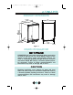
30005_CLRCO2075 User Manual 8/22/03 4:24 PM Page 5 PRODUCT DIMENSIONS 24" (61) 23-15/16" (60.8) 34-1/8" (86.7) FULL RETRACT HEIGHT WATER CONNECTION WATER VALVE 21-3/4" (55.2) WATER DRAIN CLRCO001 Figure 1 DRAIN INSTALLATION PLEASE READ all instructions completely before attempting to install or operate the unit.
30005_CLRCO2075 User Manual 8/22/03 4:24 PM Page 6 User’s Manual The CLRCO2075 can be installed using a gravity drain or can use a factory installed or equivalent drain pump. Follow these guidelines when installing drain lines to prevent water from flowing back into the ice maker storage bin and/or potentially flowing onto the floor causing water damage: Gravity Drain • Drain lines must have a 5/8 inch inside diameter.
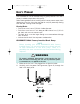
30005_CLRCO2075 User Manual 8/22/03 4:24 PM Page 7 3. Remove screws securing back panel. 4. Check that the clamps and hose connections (Figure 3) are tight at the following areas: • Discharge tube (A) • Drain tube (B) • Vent tube (C) B B C A BACK VIEW SIDE VIEW CLRCO003 Figure 3 5. Place a suitable container beneath the pump’s discharge tube. (The bucket must be able to hold a minimum of one gallon.) ! WARNING Back panel serves as a guard.
30005_CLRCO2075 User Manual 8/22/03 4:24 PM Page 8 User’s Manual CONNECTING A DRAIN PUMP If a gravity drain connection is not available, and you have not purchased the CLRCO2075 with factory installed pump, we strongly recommend the use of the U-Line P60 drain pump. The U-Line P60 drain pump is available through your Dealer, or direct from U-Line with complete installation instructions.
30005_CLRCO2075 User Manual 8/22/03 4:24 PM Page 9 SITE PREPARATION 1. Position the unit on a flat, level surface, capable of supporting the entire weight of the unit. Remember that the unit will be significantly heavier once it is fully loaded. It is extremely important that the unit is level. If it is not level, the water will not flow over the ice mold evenly.
30005_CLRCO2075 User Manual 8/22/03 4:24 PM Page 10 User’s Manual NOTE All U-Line units have a zero clearance for the door to open (Figure 4). See BUILTIN INSTALLATION for additional clearance requirements. CABINET OR WALL DOOR SWING 0" CLEARANCE NEEDED NOTE Stainless Steel models require a minimum of 2-1/2" door handle clearance when installed against a wall. UL124A Figure 4 Install and connect the water supply line. See CONNECTING THE WATER SUPPLY for installation requirements. 7.
30005_CLRCO2075 User Manual 8/22/03 4:24 PM Page 11 BUILT-IN INSTALLATION Your U-Line product has been designed for either free-standing or builtin installation. When built-in, your U-Line product does not require additional air space for top, sides or rear. However, the front grille must NOT be obstructed. CAUTION Do not install unit behind closed doors. Table 3.
30005_CLRCO2075 User Manual 8/22/03 4:24 PM Page 12 User’s Manual CONNECTING THE WATER SUPPLY When connecting the water supply, follow these guidelines: • Review the local plumbing codes before you install the unit. • In most instances, the cold water supply will come from the basement through a hole in the floor. • The water pressure should be between 20 minimum and 120 maximum psi. • Install a shut-off valve in the 1/4 inch supply line.
30005_CLRCO2075 User Manual 3. 8/22/03 4:24 PM Page 13 For recessed installations, allow extra water supply and drain line length to provide slack for easy removal from the recessed area (Figure 8). This will also safeguard against kinking the line. CLRCO005 Figure 8 NOTE After completing the installation, turn on the water and recheck water and drain connection for leaks. Apply additional tightening if needed. DO NOT use thread sealing compound or tape. 4. Plug in the power cord. 5.
30005_CLRCO2075 User Manual 8/22/03 4:24 PM Page 14 User’s Manual LEVELING THE UNIT It is extremely important that the unit is level. If it is not level, the water will not flow over the ice mold evenly. This can cause a reduction in ice rate, uneven sized cubes or water spilling into the storage area which will cause the ice in the bin to melt prematurely. Remember that floors near drains have a tendency to slope towards the drain. 1.
30005_CLRCO2075 User Manual 2. 8/22/03 4:24 PM Page 15 If the ice maker is not level, adjust the feet on the corners of the unit as necessary (Figure 11). RAISE LOWER DWR005 Figure 11 3. Check the levelness after each adjustment and repeat the previous steps until the unit is level. REVERSING THE DOOR All U-Line units (except Stainless Steel models) may be left or right hand opening. The door opening is easily reversed by moving the hinge hardware to the opposite side (Figure 12).
30005_CLRCO2075 User Manual 8/22/03 4:24 PM Page 16 User’s Manual 1. Remove top hinge screw pin (7/64" Allen wrench) from cabinet (Figure 13). Remove door by tilting forward and lifting off bottom hinge pin. 3. Remove top hinge (3 screws), reinstall hinge screw pin, and remount on opposite side BOTTOM (Figure 15). HINGE SCREW PIN UL313 Figure 15 UL310 Figure 13 2. Remove plastic screw plugs (3 each, top and bottom) from new hinge location. Do not discard (Figure 14). 4.
30005_CLRCO2075 User Manual 8/22/03 4:24 PM Page 17 5. Remove existing bottom hinge (3 screws) and remount on opposite side TOP. Remove hinge screw pin. 6. With bottom of door facing up, remove pivot plate (2 screws), flip over, and remount on opposite side of door (Figure 17). UL319 Figure 17 7. Holding door upright with top of door tilted forward, place hole of door pivot plate on bottom hinge screw pin (Figure 18).
30005_CLRCO2075 User Manual 8/22/03 4:24 PM Page 18 User’s Manual DOOR ADJUSTMENT Your door is aligned at the factory before shipment. Occasional re-adjustment may be necessary, especially if an Overlay Panel is installed. The following procedure will correct for up to 1/4" alignment. The door should never be flush with the top of the cabinet. Even when level, the top edge of the door will be 1/8" below the top of the cabinet (Figure 19). To adjust : 1.
30005_CLRCO2075 User Manual 4. 8/22/03 4:24 PM Page 19 If door edge opposite the hinges needs to move up, move plate toward outside of door. If door edge needs to move down, move plate toward inside of door (Figure 21). Repeat until top edge of door is parallel with top of cabinet and tighten screws securely. SLOTTED MOUNTING HOLES NOTCH RAISE OUTSIDE DOOR EDGE LOWER OUTSIDE DOOR EDGE CLRCO001a Figure 21 5.
30005_CLRCO2075 User Manual 8/22/03 4:24 PM Page 20 User’s Manual CUSTOM DOOR PANELS Two types of custom door panels can be installed on your U-Line unit to harmonize with or accent the surrounding decor. FULL OVERLAY DOOR PANEL A full overlay door panel completely covers the door frame and handle to give a built-in appearance.
30005_CLRCO2075 User Manual 8/22/03 4:24 PM Page 21 Install the insert as follows: ! WARNING Insert edges may be SHARP! Use care when installing. 1. Remove top hinge screw pin (7/64" Allen wrench, Figure 24). Remove door by tilting forward and lifting off bottom hinge pin. 2. Pull door gasket out of groove (top edge of door only). Start in the middle and pull outward, moving toward the edge (Figure 25). This may take some force. Do not remove the three screws behind gasket. 3.
30005_CLRCO2075 User Manual 8/22/03 4:24 PM Page 22 User’s Manual INITIAL START-UP Once installation and leveling is complete, the unit is ready for initial start-up and operation. Your unit is shipped in the ON position, however, you may turn it ON/OFF using the cycle selector switch located in the grille (Figure 27). C L N O F F O N C L N O F F O N The temperature controller will display even when the cycle selector switch is in the OFF position. CYCLE SELECTOR SWITCH UL316C Figure 27 1.
30005_CLRCO2075 User Manual 8/22/03 4:24 PM Page 23 After the first slab of ice is produced, ice production will stop until the refrigerator side of the CLRCO2075 reaches the set point temperature. After the refrigerator reaches temperature, ice production will begin again. It is possible that dirt or scale will dislodge in the water line. Always throw away all ice cubes made during the first two to three hours of operation.
30005_CLRCO2075 User Manual 8/22/03 4:24 PM Page 24 User’s Manual Refer to Table 1 to determine indicator light status. LED 1 2 Status • Solid • Flashing • Solid 3 • Flashing • Solid • Flashing Indicates • Refrigerator Temperature displayed • Not Applicable • Service Menu – wait 10 seconds and it will exit automatically • Open Thermistor – call for service • Service Menu – wait 10 seconds and it will exit automatically • Drain Pump Blocked – check installation and drain line. Call for service.
30005_CLRCO2075 User Manual 8/22/03 4:24 PM Page 25 CLEAR ICE MAKER OPERATION The ice maker side is designed to make clear ice from most water sources on a consistent basis. Water is constantly circulated over the evaporator assembly. As the water freezes, gravity causes any sediment to drop into the water trough and not become imbedded in the ice. This gives a clearer ice cube with a low mineral content. When the ice reaches the desired thickness, it falls off the evaporator and into the storage bin.
30005_CLRCO2075 User Manual 8/22/03 4:24 PM Page 26 User’s Manual The ice cube thickness control is factory set for best overall performance. The factory setting is designed to maintain an ice bridge of approximately 1/16" to 1/8" under normal conditions resulting in a dimple of approximately 1/4" to 1/2" in depth (Figure 30). A fuller cube with less of a dimple results in a thicker ice bridge. As the ice bridge becomes thicker, the tendency for the cubes to stay together as a slab increases.
30005_CLRCO2075 User Manual 2. 8/22/03 4:24 PM Page 27 Remove the screws securing the front access panel (Figure 31). ICE CUBE THICKNESS ADJUSTMENT DIAL -2 -5 -3 -4 -1 0 1 3 4 5 2 DIAL IS FACTORY SET TO “0” CLRCO031 Figure 32 3. Locate the ice cube thickness adjustment dial on the control board (Figure 32). Turn the dial clockwise (+ number) to thicken or counterclockwise (- number) to thin the ice bridge.
005_CLRCO2075 User Manual 8/22/03 4:24 PM Page 28 User’s Manual SAMPLE AREA ICE005 Figure 33 4. Reinstall front access cover. 5. Reconnect power to ice maker. 6. Empty ice bucket. GLASS SHELF REMOVAL/INSTALLATION On units with right-hand hinges, open door fully, grasp shelf firmly, lift front edge slightly and pull straight out. On units with left-hand hinges, refer below. Removal (Figure 34) 1. Pull shelf out about 6" until back of shelf clears the “hump” on the right hand side. 1 3 2 2.
30005_CLRCO2075 User Manual 8/22/03 4:24 PM Page 29 Adjustment/Installation 1. To move to a different position in the unit, insert shelf at an angle, approximately 15-20°, over the rib in the side of the unit where you want to place the shelf. The shelf must be started into the unit at an angle to clear the door. 2. Continue to slide the shelf into the unit at an angle until it clears the door. Lower the shelf and rest it on the rib. DOOR SHELF REMOVAL/INSERTION To Remove Door Shelf (Figure 35): 1.
30005_CLRCO2075 User Manual 8/22/03 4:24 PM Page 30 User’s Manual PERIODIC CLEANING AND USER MAINTENANCE Periodic cleaning and proper maintenance will ensure efficiency, top performance, and long life. The maintenance intervals listed are based on normal conditions. You may want to shorten the intervals if you have pets, the unit is used outdoors, or other special considerations. EXTERIOR CLEANING — AS REQUIRED The door, grille and cabinet may be cleaned with a mild detergent and warm water solution.
30005_CLRCO2075 User Manual 8/22/03 4:24 PM Page 31 ! WARNING • DO NOT use solvent cleaning agents or abrasives on the interior. These cleansers may transmit taste to the ice cubes, or damage or discolor the interior. CONDENSER CLEANING — EVERY 3 MONTHS To maintain operational efficiency, clean the condenser every three months (depending on environment conditions, more or less frequent cleaning may be necessary). ! WARNING Disconnect electric power to the ice maker before cleaning the condenser.
30005_CLRCO2075 User Manual 8/22/03 4:24 PM Page 32 User’s Manual 1. Remove the screws at each end of the grille. 2. Remove the grille. ! WARNING DO NOT touch the condenser fins. The condenser fins are SHARP and can be easily damaged. CAUTION DO NOT use any type of cleaner on the condenser unit. 3. Clean the condenser coil using a soft brush with a “combing” action or vacuum cleaner. Do not touch the condenser coil. 4. Position the grille to align the screw holes with the cabinet. 5.
30005_CLRCO2075 User Manual 8/22/03 4:24 PM Page 33 Ice machine cleaner is used to remove lime scale and other mineral deposits. Refer to the following steps for mineral deposit removal. The refrigerator side does not operate during the ice maker cleaning cycle. Remove all fresh food to prevent spoilage. CAUTION Never use anything to force ice from the evaporator. Damage may result. Always remove perishables before cleaning. 1.
30005_CLRCO2075 User Manual 8/22/03 4:24 PM Page 34 User’s Manual 9. When the self-cleaning process stops (approximately 45 minutes), clean the storage bin. 10. Wipe down the interior and storage bin with a solution of nonabrasive mild soap or detergent and warm water. Rinse with clean water. 11. Sanitize the bin with a solution of 1 tablespoon of bleach in 1 gallon of warm water. Rinse thoroughly with clean water. 12. Move the cycle selector switch to the ON position to resume ice production.
30005_CLRCO2075 User Manual 8/22/03 4:24 PM Page 35 INLET SCREEN CLEANING — EVERY YEAR The solenoid valve inlet screen must be cleaned at least once each year as follows: 1. Shut off the water at the water supply valve. 2. Pull the unit out to access the back panel. 3. Disconnect electrical power to the unit. 4. Disconnect the hose connector from the water solenoid valve (Figure 39). 5. Use a tooth brush to clean sediment from the inlet screen. DO NOT remove the screen. 6.
30005_CLRCO2075 User Manual 8/22/03 4:24 PM Page 36 User’s Manual LIGHT BULB REPLACEMENT Light bulb replacement Échelon™ series is simple. 1. 2. in the Remove the light housing cover by sliding the cover toward the tab, swinging the end opposite the tab down and pulling down and away (Figure 40). Replace bulb with genuine U-Line #31317 replacement. 1 TAB 2 U-Line P/N 31317 3.
30005_CLRCO2075 User Manual 8/22/03 4:24 PM Page 37 STORAGE, VACATION AND MOVING If the unit is to be stored, moved or not used for extended periods, it will be necessary to drain the system of water. ! WARNING Electrical Shock Hazard. Disconnect power before servicing. Before operating replace all panels. Failure to do so can result in death or electrical shock. 1. Disconnect power from the unit. 2. Remove ice from the storage bin. 3. Shut off water supply at the main water source. 4.
30005_CLRCO2075 User Manual 8/22/03 4:24 PM Page 38 User’s Manual FRONT COVER OVERFLOW CLRCO012 UL208 Figure 41 7. Clean the ice maker and storage bin before next use. 8. Prop door open to allow for air circulation and prevent mold and mildew. It is possible that dirt or scale will dislodge in the water line. Always throw away all ice cubes made during the first 24 hours of operation when the unit is returned to service.
30005_CLRCO2075 User Manual 8/22/03 4:24 PM Page 39 TROUBLESHOOTING BEFORE CALLING FOR SERVICE If the unit appears to be malfunctioning, read through NORMAL OPERATION first. If the problem persists, check the TROUBLESHOOTING GUIDE. Locate the problem in the guide and refer to the cause and its remedy before calling for service. The problem could be something very simple which can be solved without a service call.
30005_CLRCO2075 User Manual 8/22/03 4:24 PM Page 40 User’s Manual Problem The unit is not cold enough. Possible Cause Light staying on. Remedy Call for service. Dirty condenser coils. Clean condenser. Refer to CONDENSER CLEANING. Airflow must not be obstructed to front grille. Refer to INSTALLATION. Use the temperature controller to set temperature colder. Allow 24 hours for temperature to stabilize. Make sure no obstructions are blocking the door and unit is level. Refer to LEVELING THE UNIT.
30005_CLRCO2075 User Manual Problem Unit runs but produces very little ice. 8/22/03 4:24 PM Page 41 Possible Cause Dirty condenser coils. High air temperature around unit. Scale and mineral buildup in unit. Inadequate airflow at the front of the unit. Cleaning Cycle recently performed. Ice is slow to release or does not release from the evaporator. Ice-making system is dirty. Poor ice quality. (soft or unclear) Unit is not level. Poor incoming water quality. Ice-making system is dirty.
30005_CLRCO2075 User Manual 8/22/03 4:24 PM Page 42 User’s Manual Problem Unit produces shallow or incomplete cubes, or the ice fill pattern on the evaporator is incomplete. Possible Cause Low water level. Water leaking from under the unit. Supply line leaking. Hot incoming water. Incorrect incoming water pressure. Unit is not level. Bin drain leaking. Ice storage bin full of water. Obstructed drain. Remedy Check to see that overflow tube is fully seated. Connect the unit to a cold water supply.
30005_CLRCO2075 User Manual 8/22/03 4:24 PM 43 Page 43
30005_CLRCO2075 User Manual 8/22/03 4:24 PM User’s Manual 44 Page 44
30005_CLRCO2075_UM_Cover.
30005_CLRCO2075_UM_Cover.qxd 8/22/03 4:27 PM Page 1 É c h e l o n™ P. O . B o x 2 4 5 0 4 0 Milwaukee, WI 53224-9540 Phone: 414.354.0300 Fax: 414.354.7905 w w w . u - l i n e . c o m U S E R M P r i n t e d i n U . S . A . P / N 3 0 0 0 5 ( R e v.