™ Installation Guide CO2075FF — Ice Maker/Refrigerator www.U-LineService.com Phone (414) 354-0300 • FAX (414) 354-7905 Service & Parts Tech Lines Phone (800) 779-2547 • FAX (414) 354-5696 OnlineService@U-Line.
™ CO2075FF — Ice Maker/Refrigerator Contents Exterior Cleaning . . . . . . . . . . . . . . . . . . . . . . . . . . . . . . Cut-Out Dimensions . . . . . . . . . . . . . . . . . . . . . . . . . . . Product Dimensions . . . . . . . . . . . . . . . . . . . . . . . . . . . . Door Swing/Clearances Information . . . . . . . . . . . . . . Reversing the Door. . . . . . . . . . . . . . . . . . . . . . . . . . . . . Other Site Requirements . . . . . . . . . . . . . . . . . . . . . . . .
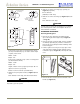
™ CO2075FF — Ice Maker/Refrigerator General Precautions 2 Inspect and Plan Use this appliance for its intended purpose only and follow these general precautions along with those listed throughout this guide: You have received a carton containing your CO2075FF Ice Maker/Refrigerator with a package inside containing a User Manual, a Product Registration Card and water connection parts. Complete and mail the Product Registration Card or register online at www.U-LineService.com.
™ CO2075FF — Ice Maker/Refrigerator After all the protective coating has been removed from the unit/door, clean all Stainless Steel surfaces with Claire Stainless Steel Polish and Cleaner or comparable product or a mild detergent and warm water solution and soft cloth. Do NOT use abrasive cleaning agents.
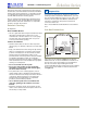
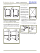
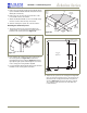
™ CO2075FF — Ice Maker/Refrigerator Product Dimensions Reversing the Door (Black and White Units Only) 25-13/16" Including Handle 23-11/16" Including Handle 34-1/8" 34-1/8" 23-15/16" Black and White All U-Line units (except Stainless Steel models) may be left- or right-hand opening. The door opening is easily reversed by moving the hinge hardware to the opposite side.
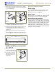
CO2075FF — Ice Maker/Refrigerator ™ Other Site Requirements 4. Remove the two door closer inserts from the existing bottom hinge and install as shown on the new bottom hinge (see Figure 8). Power Supply The unit requires a grounded and polarized 115 VAC, 60 Hz, 15A circuit (normal household current). See Electrical Specifications on Page 14. Hinge Screw Pin Water Supply Door Closer Inserts The unit requires a 1/4-inch OD water supply line and a shut-off valve. For more information see Page 13.
™ CO2075FF — Ice Maker/Refrigerator Side-By-Side Installation Instructions 4 Prepare and Install Door Panel (Black and White Units Only) For a complete refreshment center, install your CO2075FF Ice Maker/Refrigerator beside a U-Line Drawer or Wine Captain Model (see Figure 11 for typical cut-out). Note that each Side-By-Side Installation will be different.
™ CO2075FF — Ice Maker/Refrigerator Full Overlay Door Panel Door Panel Preparation A full overlay door panel completely covers the doorframe and handle to give a built-in appearance. See your U-Line dealer for the optional Full Overlay Door Panel Kit (P/N U-OL2075B — Black or P/N U-OL2075W — White). Appropriate hardware, Modified Handle, Replacement Hinges and a copy of these instructions will be included in the kit. Figure 12 1. Cut the overlay to the following dimensions (see Figure 15).
™ 13/32" CO2075FF — Ice Maker/Refrigerator 0.177" Dia. (#16 Drill) x 11/16" Deep 4. Drill hole for upper door hinge (top of panel) (see Figure 16, Top View). 13/32" 0.177" diameter (#16 drill) x 11/16" deep 3/8" 3/8" 5. Drill hole for lower door hinge (see Figure 16, Bottom View). Door Bottom: 5/16" Dia.
™ CO2075FF — Ice Maker/Refrigerator 5. Remove the top handle and discard. (This handle will be replaced with the Modified Handle included in the Full Overlay Door Panel Kit.) Tape Back of Wood Panel Removed Door Panel 6. Remove the two screws located on both sides of the lower handle. Remove the handle. 7. Attach the Modified Handle to the lower handle using the three screws removed in Step 4. Set aside. 8. Slide the existing door panel out of the doorframe.
™ CO2075FF — Ice Maker/Refrigerator Typical Wood Panel Door Panel Pivot Post Wood Panel Top Hinge Plate (5/8" Longer than Existing Top Hinge Plate) Top Pivot Plate #10 x 5/8" Round Head Screw Seven Required #8-32 x 1/2" Flat Head Screw Three Places Plastic Spacer Seven Required Top Pivot Plate Figure 22 Door Panel 5. Remove the existing bottom pivot plate and replace with the Full Overlay pivot plate (see Figure 23). Figure 24 3.
™ CO2075FF — Ice Maker/Refrigerator 5 Adjust Door Checking Door Alignment The unit’s door is aligned at the factory before shipment. However, its alignment could have been disturbed during shipment or during door panel installation. Slotted Mounting Holes Notch IMPORTANT Properly aligned, the door should be 1/8" below the top of the unit’s cabinet, NOT flush with the top (see Figure 26). Raise Outside Door Edge Lower Outside Door Edge Figure 28 1/8" 3. See Figure 28.
™ CO2075FF — Ice Maker/Refrigerator 2. Locate the compression fitting and ferrule packed with the unit. Slide the compression fitting and ferrule over the 1/4-inch OD water supply line. Do not use thread sealing compound or tape. Using two wrenches, tighten the compression fitting on the supply line (see Figure 31). 6 Prepare Plumbing CAUTION Plumbing installation must observe all state and local codes. All water connections MUST BE made by a licensed/ qualified plumbing contractor.
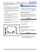
™ CO2075FF — Ice Maker/Refrigerator 7 Prepare Power Supply 8 Level the Unit Electrical Specifications Leveling Information CAUTION IMPORTANT It is extremely important that the unit is level. If it is not level, the ice mold will not fill evenly. Electrical installation must observe all state and local codes. This unit requires connection to a grounded (threeprong), polarized receptacle that has been placed by a qualified electrician. 1.
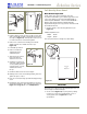
™ CO2075FF — Ice Maker/Refrigerator Door Shelves 9 Install the Unit 1. First pull shelf up at a 45° angle, then straight out (see Figure 37). Installation of the CO2075FF 1. Open the water supply valve in the main water source. Notch 2. Choose new location and line up on bosses. First push straight in, then down at a 45° angle. 2. Make sure the cycle selector switch is in the OFF (middle) position (see Figure 38). 3. Plug in the power cord. Boss 4. Gently push the unit into position.
™ CO2075FF — Ice Maker/Refrigerator About Settings 10 Start-Up for the First Time No adjustments should be necessary at this time. For information about Adjusting the Temperature Control and Adjusting the Cube Size, see the User Manual. Initial Start-Up Once installation and leveling is complete, the unit is ready for initial start-up and operation. The ON/OFF switch is located in the front grille (see Figure 38).
™ Who to Call Service Information If the need for service arises, contact the dealer from whom the unit was purchased. State the Model Number and Serial Number and explain the problem. The Model and Serial Number plate is located inside unit at upper right hand corner. If you need to locate a service company, you can go online at www.U-LineService.com and search for a service company by zip code.