USER GUIDE SAFETY • INSTALLATION & INTEGRATION • OPERATING INSTRUCTIONS • MAINTENANCE • SERVICE RIGHT PRODUCT. RIGHT PLACE. RIGHT TEMPERATURE. SINCE 1962.
USER GUIDE u-line.
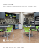
USER GUIDE u-line.com WELCOME TO U-LINE Congratulations on your U-Line purchase. Your product comes from a company with over five decades and three generations of premium modular ice making, refrigeration, and wine preservation experience. U-Line continues to be the American leader, delivering versatility and flexibility for multiple applications including residential, light commercial, outdoor and marine use.
USER GUIDE u-line.com SAFETY • INSTALLATION & INTEGRATION • OPERATING INSTRUCTIONS • MAINTENANCE • SERVICE Safety and Warning NOTICE Please read all instructions before installing, operating, or servicing the appliance.
USER GUIDE u-line.com SAFETY • INSTALLATION & INTEGRATION • OPERATING INSTRUCTIONS • MAINTENANCE • SERVICE Disposal and Recycling ! DANGER RISK OF CHILD ENTRAPMENT. Before you throw away your old refrigerator or freezer, take off the doors and leave shelves in place so children may not easily climb inside.
USER GUIDE u-line.com SAFETY • INSTALLATION & INTEGRATION • OPERATING INSTRUCTIONS • MAINTENANCE • SERVICE Environmental Requirements This model is intended for indoor/interior applications only and is not to be used in installations that are open/ exposed to natural elements. This unit is designed to operate between 50°F (10°C) and 100°F (38°C). Higher ambient temperatures may reduce the unit’s ability to reach low temperatures and/or reduce ice production on applicable models.
USER GUIDE u-line.com SAFETY • INSTALLATION & INTEGRATION • OPERATING INSTRUCTIONS • MAINTENANCE • SERVICE Electrical ! WARNING SHOCK HAZARD — Electrical Grounding Required. Never attempt to repair or perform maintenance on the unit until the electricity has been disconnected. Never remove the round grounding prong from the plug and never use a two-prong grounding adapter.
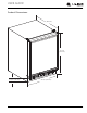
USER GUIDE u-line.com SAFETY • INSTALLATION & INTEGRATION • OPERATING INSTRUCTIONS • MAINTENANCE • SERVICE Cutout Dimensions PREPARE SITE Your U-Line product has been designed for either freestanding or built-in installation. When built-in, your unit does not require additional air space for top, sides, or rear. However, the front grille must NOT be obstructed, and clearance is required for an electrical connection in the rear. ! CAUTION Unit can NOT be installed behind a closed cabinet door.
USER GUIDE u-line.
USER GUIDE u-line.com SAFETY • INSTALLATION & INTEGRATION • OPERATING INSTRUCTIONS • MAINTENANCE • SERVICE Side-by-Side Installation Two units may be installed side-by-side. Cutout width for a side-by-side installation is the cutout dimension of a single unit times two. No trim kit is required. However, 1/4" (6 mm) of space 3. Place bracket over holes and attach to unit with two screws removed in step 2 using a T-25 Torx driver. Tighten screws fully. 4. Gently push units into position.
USER GUIDE u-line.com SAFETY • INSTALLATION & INTEGRATION • OPERATING INSTRUCTIONS • MAINTENANCE • SERVICE Water Hookup PREPARE PLUMBING ! CAUTION The water valve uses a standard 1/4" (6.35 mm) Do not use any plastic water supply line. The line compression fitting. U-Line recommends using accessory is under pressure at all times. Plastic may crack water hook up kit – part # WATERHOOKUP.
USER GUIDE u-line.com SAFETY • INSTALLATION & INTEGRATION • OPERATING INSTRUCTIONS • MAINTENANCE • SERVICE 9. Install retaining clip. 3. Locate water valve inlet. 4. Break away filler feature in bushing with flat screwdriver. Remove ZLWK ɠDW screwdriver 5. Thread water line through back panel hole (with bushing). 6. Locate water valve inlet and connect to valve. 7. Turn on water supply and check for leaks. 8. Reinstall back panel.
USER GUIDE u-line.com SAFETY • INSTALLATION & INTEGRATION • OPERATING INSTRUCTIONS • MAINTENANCE • SERVICE General Installation LEVELING INFORMATION INSTALLATION 1. Plug in the power/electrical cord. 2. Gently push the unit into position. Be careful not to NOTICE Because these units do not have leveling legs, it entangle the cord and water line. is extremely important that they sit on a level surface. If they are not level, the ice mold will 3.
USER GUIDE u-line.com SAFETY • INSTALLATION & INTEGRATION • OPERATING INSTRUCTIONS • MAINTENANCE • SERVICE Integrated Panel Dimensions INSERT CUSTOM 1/4'' THICK DOOR PANEL Insert Panel Preparation A custom door panel may be inserted into the door frame. Custom door panels can be flat or raised, as long as the maximum panel thickness where inserted into the door reveal (channel) is no more than 1/4" thick. For raised panels, the depth of the reveal is 1/4" on all four sides.
USER GUIDE u-line.com SAFETY • INSTALLATION & INTEGRATION • OPERATING INSTRUCTIONS • MAINTENANCE • SERVICE Integrated Panel Installation 5. Slide custom door panel insert into 1/4" (6 mm) channel in door front. This model accepts a 1/4" insert panel. INSERT PANEL INSTALLATION NOTICE Install the insert as follows: Use care not to damage magnet, located on door bottom when installing door insert. Do not set door on bottom edge when pushing insert into ! CAUTION Use care when handling the insert.
USER GUIDE u-line.com SAFETY • INSTALLATION & INTEGRATION • OPERATING INSTRUCTIONS • MAINTENANCE • SERVICE Grille - Plinth Installation 1 3 REMOVING AND INSTALLING GRILLE ! WARNING Disconnect electric power to the unit before 4 2 removing the grille. When using the unit, the grille (plinth strip/base fascia) must be installed. ! WARNING DO NOT touch the condenser fins. The condenser fins are SHARP and can be easily damaged. Removing the grille 1. Disconnect power to the unit. 2.
USER GUIDE u-line.com SAFETY • INSTALLATION & INTEGRATION • OPERATING INSTRUCTIONS • MAINTENANCE • SERVICE Door Swing All units have a zero clearance for the door to open 90°. U-Line recommends a minimum door clearance of 1/4" (6 mm) to accommodate the handle if the unit is installed next to a wall. 1/4" Min.
USER GUIDE u-line.com SAFETY • INSTALLATION & INTEGRATION • OPERATING INSTRUCTIONS • MAINTENANCE • SERVICE Door Adjustments CHECKING DOOR ALIGNMENT The unit’s door is aligned at the factory before shipment. However, its alignment could have been disturbed during shipment. NOTICE To reverse the door mounting, perform the following: 1. Remove grille (see GRILLE-PLINTH INSTALLATION). 2. Remove top hinge from cabinet (three screws). Hold door to keep it from falling.
USER GUIDE u-line.com SAFETY • INSTALLATION & INTEGRATION • OPERATING INSTRUCTIONS • MAINTENANCE • SERVICE 6. Install hinge on opposite side at bottom of cabinet. 9. Remove plastic hole plug from door handle and Align hinge outer edge with cabinet before tightening relocate to opposite side. Lift the handle slightly and screws. press on the locking tab, then gently pry the hole plug out of the hole, being careful not scratch the top cap.
USER GUIDE u-line.com SAFETY • INSTALLATION & INTEGRATION • OPERATING INSTRUCTIONS • MAINTENANCE • SERVICE First Use All U-Line controls are preset at the factory. Initial startup requires no adjustments. NOTICE U-Line recommends allowing the unit to run overnight before loading with product. U-Line recommends discarding the ice produced during the first two to three hours of operation to avoid possible dirt or scale that may dislodge from the water line.
USER GUIDE u-line.com SAFETY • INSTALLATION & INTEGRATION • OPERATING INSTRUCTIONS • MAINTENANCE • SERVICE Ice ! CAUTION ICE MAKER OPERATION When the ice bucket is full, the ice making mechanism will NEVER use an ice pick, knife or other sharp shut off. However, the refrigeration system will continue instrument to separate cubes. Shake the ice to cool and maintain the ice supply. bucket instead.
USER GUIDE u-line.com SAFETY • INSTALLATION & INTEGRATION • OPERATING INSTRUCTIONS • MAINTENANCE • SERVICE 3. Turn the adjusting screw toward the minus (-) sign ICE MAKER ADJUSTMENT (clockwise) for smaller cubes or toward the plus (+) Ice Cube Thickness Adjustment sign (counterclockwise) for larger cubes. Interval - As Required On ice maker equipped models, adjust the cube size by changing water amount injected into the ice maker 4. Install the ice maker assembly cover.
USER GUIDE u-line.com SAFETY • INSTALLATION & INTEGRATION • OPERATING INSTRUCTIONS • MAINTENANCE • SERVICE Airflow and Product Loading NOTICE The unit requires proper airflow to perform at its highest efficiency. Do not block the front grille, or the unit will not perform as expected. Do not install the unit behind a door. When loading your unit, leave space between the evaporator and product loaded. Anything in direct contact with the evaporator is subject to freezing.
USER GUIDE u-line.com SAFETY • INSTALLATION & INTEGRATION • OPERATING INSTRUCTIONS • MAINTENANCE • SERVICE Interior Shelves NOTICE REMOVING AND INSTALLING INTERIOR SHELVES Make sure the shelves are inserted fully into the unit. The edge strip toward the rear prevents cans and bottles from freezing against the cold evaporator. 3 1 2 For models equipped with glass shelves having recessed shelf supports, remove the shelves as follows: 1.
USER GUIDE u-line.com SAFETY • INSTALLATION & INTEGRATION • OPERATING INSTRUCTIONS • MAINTENANCE • SERVICE Door Shelves REMOVING AND INSTALLING DOOR SHELVES 1 2 To remove the door shelf: 1. Grasp shelf in center, and lift until the shelf notches (1) clear the pins (2). 2. Carefully pull the shelf away from the door. To install the door shelf: 1. Holding the shelf in the center, center the shelf in the door at the desired location, slightly above the pins (2). 2. Lower the shelf onto the pins (2).
USER GUIDE u-line.com SAFETY • INSTALLATION & INTEGRATION • OPERATING INSTRUCTIONS • MAINTENANCE • SERVICE Cleaning If any surface discoloring or rusting appears, clean it EXTERIOR CLEANING a nonabrasive cloth. Always clean with the grain. Always Vinyl Clad (Black or White) Models finish with Claire® Stainless Steel Polish and Cleaner or quickly with Bon-Ami® or Barkeepers Friend Cleanser® and Clean surfaces with a mild detergent and warm water comparable product to prevent further problems.
USER GUIDE u-line.com SAFETY • INSTALLATION & INTEGRATION • OPERATING INSTRUCTIONS • MAINTENANCE • SERVICE DEFROSTING Manual Defrost Models 7. Prop the door in an open position (2 in. [50 mm] minimum). Unit is a manual defrost model and will require occasional defrosting. When there is build-up of 1/4" (6 mm) or more of frost, manually defrost the unit. Defrost every two 8. After about 1 hour remove the ice bin and discard water. months minimum. 9. Allow the frost to melt naturally.
USER GUIDE u-line.com SAFETY • INSTALLATION & INTEGRATION • OPERATING INSTRUCTIONS • MAINTENANCE • SERVICE Cleaning Condenser INTERVAL - EVERY SIX MONTHS To maintain operational efficiency, keep the front grille free of dust and lint, and clean the condenser when necessary. Depending on environmental conditions, more or less frequent cleaning may be necessary. ! WARNING Disconnect electric power to the unit before cleaning the condenser. ! WARNING DO NOT touch the condenser fins.
USER GUIDE u-line.com SAFETY • INSTALLATION & INTEGRATION • OPERATING INSTRUCTIONS • MAINTENANCE • SERVICE Extended Non-Use VACATION/HOLIDAY, PROLONGED SHUTDOWN For questions regarding winterization, please The following steps are recommended for periods of call U-Line at +1.800.779.2547. extended non-use: 1. Remove all consumable content from the unit. 2. Disconnect the power cord from its outlet/socket and leave it disconnected until the unit is returned to service.
USER GUIDE u-line.com SAFETY • INSTALLATION & INTEGRATION • OPERATING INSTRUCTIONS • MAINTENANCE • SERVICE Troubleshooting • Evaporator: Refrigerant flowing through an evaporator may sound like boiling liquid. BEFORE CALLING FOR SERVICE If you think your U-Line product is malfunctioning, read the CONTROL OPERATION section to clearly understand the function of the control.
USER GUIDE u-line.com SAFETY • INSTALLATION & INTEGRATION • OPERATING INSTRUCTIONS • MAINTENANCE • SERVICE Problem Possible Cause and Remedy Product Is Freezing. Because product in contact with the rear wall may freeze, ensure no product is touching the rear wall. Adjust the temperature to a warmer set point. Product Is Not Cold Enough. Air temperature does not indicate product temperature. See CHECKING PRODUCT TEMPERATURE below. Adjust the temperature to a cooler set point.
USER GUIDE u-line.com SAFETY • INSTALLATION & INTEGRATION • OPERATING INSTRUCTIONS • MAINTENANCE • SERVICE Warranty unit is completed and mailed back or electronically U-LINE CORPORATION LIMITED WARRANTY apply to cosmetic damages. A proof of purchase may 1. U-Line Corporation (“U-Line”) warrants each U-Line be required. submitted to U-Line.
USER GUIDE u-line.com SAFETY • INSTALLATION & INTEGRATION • OPERATING INSTRUCTIONS • MAINTENANCE • SERVICE of pool water, or directing a spray from a hose or similar device into and around the unit. 7. If a product defect is discovered during the applicable warranty period, you must promptly notify either U-Line at 8900 N. 55th Street, Milwaukee, Wisconsin 53223 USA or at +1.800.779.2547 or the dealer from whom you purchased the product.