USER GUIDE & SERVICE MANUAL SAFETY • INSTALLATION & INTEGRATION • OPERATING INSTRUCTIONS • MAINTENANCE • SERVICE RIGHT PRODUCT. RIGHT PLACE. RIGHT TEMPERATURE. SINCE 1962.
USER GUIDE & SERVICE MANUAL u-line.
USER GUIDE u-line.com WELCOME TO U-LINE Congratulations on your U-Line purchase. Your product comes from a company with over five decades of premium modular ice making, refrigeration, and wine preservation experience. U-Line creates products focused on functionality, style, and inspired innovations — paying close attention to even the smallest details. Applications include residential, outdoor, ADA height compliant, marine, and commercial.
USER GUIDE u-line.com SAFETY • INSTALLATION & INTEGRATION • OPERATING INSTRUCTIONS • MAINTENANCE • SERVICE Safety and Warning NOTICE Please read all instructions before installing, operating, or servicing the appliance.
USER GUIDE u-line.com SAFETY • INSTALLATION & INTEGRATION • OPERATING INSTRUCTIONS • MAINTENANCE • SERVICE Disposal and Recycling ! DANGER RISK OF CHILD ENTRAPMENT. Before you throw away your old refrigerator or freezer, take off the doors and leave shelves in place so children may not easily climb inside.
USER GUIDE u-line.com SAFETY • INSTALLATION & INTEGRATION • OPERATING INSTRUCTIONS • MAINTENANCE • SERVICE Environmental Requirements This model is intended for indoor/interior applications only and is not to be used in installations that are open/ exposed to natural elements. This unit is designed to operate between 50°F (10°C) and 100°F (38°C). Higher ambient temperatures may reduce the unit’s ability to reach low temperatures and/or reduce ice production on applicable models.
USER GUIDE u-line.com Electrical ! WARNING SHOCK HAZARD — Electrical Grounding Required. Never attempt to repair or perform maintenance on the unit until the electricity has been disconnected. Never remove the round grounding prong from the plug and never use a two-prong grounding adapter. Altering, cutting or removing power cord, removing power plug, or direct wiring can cause serious injury, fire, loss of property and/or life, and will void the warranty.
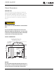
USER GUIDE u-line.com SAFETY • INSTALLATION & INTEGRATION • OPERATING INSTRUCTIONS • MAINTENANCE • SERVICE Cutout Dimensions PREPARE SITE Your U-Line product has been designed for either freestanding or built-in installation. When built-in, your unit does not require additional air space for top, sides, or rear. However, the front grille must NOT be obstructed, and clearance is required for an electrical connection in the rear. ! CAUTION Unit can NOT be installed behind a closed cabinet door.
USER GUIDE u-line.
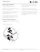
USER GUIDE Side-by-Side Installation u-line.com 3. Place bracket over holes and attach to unit with two screws removed in step 2 using a T-25 Torx driver. Two units may be installed side-by-side. Cutout width for a side-by-side installation is the cutout Tighten screws fully. 4. Gently push units into position. Be careful not to dimension of a single unit times two. No trim kit is required. However, 1/4" (6 mm) of space entangle the electrical cord or water line, if applicable. 5.
USER GUIDE u-line.com SAFETY • INSTALLATION & INTEGRATION • OPERATING INSTRUCTIONS • MAINTENANCE • SERVICE Water Hookup ! CAUTION PREPARE PLUMBING Do not use any plastic water supply line. The line The water valve uses a standard 1/4" (6.35 mm) is under pressure at all times. Plastic may crack compression fitting. U-Line recommends using accessory or rupture with age and cause damage to your water hook up kit – part # 80-54674-00. The kit includes a home.
USER GUIDE u-line.com SAFETY • INSTALLATION & INTEGRATION • OPERATING INSTRUCTIONS • MAINTENANCE • SERVICE 3. Locate water valve inlet. 9. Install retaining clip. 4. Break away filler feature in bushing with flat screwdriver. Remove ZLWK ɠDW screwdriver 5. Thread water line through back panel hole (with bushing). 6. Locate water valve inlet and connect to valve. 7. Turn on water supply and check for leaks. 8. Reinstall back panel.
USER GUIDE u-line.com SAFETY • INSTALLATION & INTEGRATION • OPERATING INSTRUCTIONS • MAINTENANCE • SERVICE General Installation INSTALLATION 1. Plug in the power/electrical cord. LEVELING INFORMATION 2. Gently push the unit into position. Be careful not to NOTICE entangle the cord and water line. Because these units do not have leveling legs, it is extremely important that they sit on a level 3. Re-check the leveling, from front to back and side to surface.
USER GUIDE u-line.com SAFETY • INSTALLATION & INTEGRATION • OPERATING INSTRUCTIONS • MAINTENANCE • SERVICE Integrated Panel Dimensions INSERT CUSTOM 1/4'' THICK DOOR PANEL Insert Panel Preparation A custom door panel may be inserted into the door frame. Custom door panels can be flat or raised, as long as the maximum panel thickness where inserted into the door reveal (channel) is no more than 1/4" thick. For raised panels, the depth of the reveal is 1/4" on all four sides.
USER GUIDE u-line.com SAFETY • INSTALLATION & INTEGRATION • OPERATING INSTRUCTIONS • MAINTENANCE • SERVICE Integrated Panel Installation 5. Slide custom door panel insert into 1/4" (6 mm) channel in door front. This model accepts a 1/4" insert panel. INSERT PANEL INSTALLATION NOTICE Install the insert as follows: Use care not to damage magnet, located on door bottom when installing door insert. Do not set door on bottom edge when pushing insert into place. ! CAUTION 6.
USER GUIDE u-line.com SAFETY • INSTALLATION & INTEGRATION • OPERATING INSTRUCTIONS • MAINTENANCE • SERVICE Grille - Plinth Installation 1 3 REMOVING AND INSTALLING GRILLE ! WARNING 4 Disconnect electric power to the unit before 2 removing the grille. When using the unit, the grille (plinth strip/base fascia) must be installed. ! WARNING DO NOT touch the condenser fins. The condenser fins are SHARP and can be easily damaged. Removing the grille 1. Disconnect power to the unit. 2.
USER GUIDE u-line.com SAFETY • INSTALLATION & INTEGRATION • OPERATING INSTRUCTIONS • MAINTENANCE • SERVICE Door Swing All units have a zero clearance for the door to open 90°. U-Line recommends a minimum door clearance of 1/4" (6 mm) to accommodate the handle if the unit is installed next to a wall. 1/4" Min.
USER GUIDE u-line.com SAFETY • INSTALLATION & INTEGRATION • OPERATING INSTRUCTIONS • MAINTENANCE • SERVICE Door Adjustments To reverse the door mounting, perform the following: CHECKING DOOR ALIGNMENT 1. Remove grille (see GRILLE-PLINTH INSTALLATION). The unit’s door is aligned at the factory before shipment. However, its alignment could have been disturbed during 2. Remove top hinge from cabinet (three screws). Hold shipment. door to keep it from falling.
USER GUIDE u-line.com SAFETY • INSTALLATION & INTEGRATION • OPERATING INSTRUCTIONS • MAINTENANCE • SERVICE 9. Remove plastic hole plug from door handle and 6. Install hinge on opposite side at bottom of cabinet. Align hinge outer edge with cabinet before tightening relocate to opposite side. Lift the handle slightly and screws. press on the locking tab, then gently pry the hole plug out of the hole, being careful not scratch the top cap.
USER GUIDE u-line.com SAFETY • INSTALLATION & INTEGRATION • OPERATING INSTRUCTIONS • MAINTENANCE • SERVICE First Use All U-Line controls are preset at the factory. Initial startup requires no adjustments. NOTICE U-Line recommends allowing the unit to run overnight before loading with product. U-Line recommends discarding the ice produced during the first two to three hours of operation to avoid possible dirt or scale that may dislodge from the water line.
USER GUIDE u-line.com SAFETY • INSTALLATION & INTEGRATION • OPERATING INSTRUCTIONS • MAINTENANCE • SERVICE Ice ! CAUTION ICE MAKER OPERATION When the ice bucket is full, the ice making mechanism will NEVER use an ice pick, knife or other sharp shut off. However, the refrigeration system will continue instrument to separate cubes. Shake the ice to cool and maintain the ice supply. bucket instead.
USER GUIDE u-line.com SAFETY • INSTALLATION & INTEGRATION • OPERATING INSTRUCTIONS • MAINTENANCE • SERVICE 3. Turn the adjusting screw toward the minus (-) sign ICE MAKER ADJUSTMENT (clockwise) for smaller cubes or toward the plus (+) Ice Cube Thickness Adjustment sign (counterclockwise) for larger cubes. Interval - As Required On ice maker equipped models, adjust the cube size by 4. Install the ice maker assembly cover.
USER GUIDE u-line.com SAFETY • INSTALLATION & INTEGRATION • OPERATING INSTRUCTIONS • MAINTENANCE • SERVICE Airflow and Product Loading NOTICE The unit requires proper airflow to perform at its highest efficiency. Do not block the front grille, or the unit will not perform as expected. Do not install the unit behind a door. When loading your unit, leave space between the evaporator and product loaded. Anything in direct contact with the evaporator is subject to freezing.
USER GUIDE u-line.com SAFETY • INSTALLATION & INTEGRATION • OPERATING INSTRUCTIONS • MAINTENANCE • SERVICE Interior Shelves NOTICE Make sure the shelves are inserted fully into the REMOVING AND INSTALLING INTERIOR SHELVES unit. The edge strip toward the rear prevents cans and bottles from freezing against the cold evaporator. 3 1 2 For models equipped with glass shelves having recessed shelf supports, remove the shelves as follows: 1.
USER GUIDE u-line.com SAFETY • INSTALLATION & INTEGRATION • OPERATING INSTRUCTIONS • MAINTENANCE • SERVICE Door Shelves REMOVING AND INSTALLING DOOR SHELVES 1 2 To remove the door shelf: 1. Grasp shelf in center, and lift until the shelf notches (1) clear the pins (2). 2. Carefully pull the shelf away from the door. To install the door shelf: 1. Holding the shelf in the center, center the shelf in the door at the desired location, slightly above the pins (2). 2. Lower the shelf onto the pins (2).
USER GUIDE u-line.com SAFETY • INSTALLATION & INTEGRATION • OPERATING INSTRUCTIONS • MAINTENANCE • SERVICE Cleaning If any surface discoloring or rusting appears, clean it EXTERIOR CLEANING a nonabrasive cloth. Always clean with the grain. Always Vinyl Clad (Black or White) Models finish with Claire® Stainless Steel Polish and Cleaner or quickly with Bon-Ami® or Barkeepers Friend Cleanser® and comparable product to prevent further problems.
USER GUIDE u-line.com SAFETY • INSTALLATION & INTEGRATION • OPERATING INSTRUCTIONS • MAINTENANCE • SERVICE 7. Prop the door in an open position (2 in. [50 mm] DEFROSTING minimum). Manual Defrost Models Unit is a manual defrost model and will require occasional 8. After about 1 hour remove the ice bin and discard defrosting. When there is build-up of 1/4" (6 mm) or more water. of frost, manually defrost the unit. Defrost every two months minimum. 9. Allow the frost to melt naturally.
USER GUIDE u-line.com SAFETY • INSTALLATION & INTEGRATION • OPERATING INSTRUCTIONS • MAINTENANCE • SERVICE Cleaning Condenser INTERVAL - EVERY SIX MONTHS To maintain operational efficiency, keep the front grille free of dust and lint, and clean the condenser when necessary. Depending on environmental conditions, more or less frequent cleaning may be necessary. ! WARNING Disconnect electric power to the unit before cleaning the condenser. ! WARNING DO NOT touch the condenser fins.
USER GUIDE u-line.com SAFETY • INSTALLATION & INTEGRATION • OPERATING INSTRUCTIONS • MAINTENANCE • SERVICE Extended Non-Use VACATION/HOLIDAY, PROLONGED SHUTDOWN For questions regarding winterization, please The following steps are recommended for periods of call U-Line at +1.800.779.2547. extended non-use: ! CAUTION 1. Remove all consumable content from the unit. Damage caused by freezing temperatures is not 2. Disconnect the power cord from its outlet/socket and covered by the warranty.
USER GUIDE u-line.com SAFETY • INSTALLATION & INTEGRATION • OPERATING INSTRUCTIONS • MAINTENANCE • SERVICE Troubleshooting • Evaporator: Refrigerant flowing through an evaporator may sound like boiling liquid. BEFORE CALLING FOR SERVICE If you think your U-Line product is malfunctioning, read • Condenser Fan: Air moving through a condenser may the CONTROL OPERATION section to clearly understand be heard. the function of the control.
USER GUIDE u-line.com SAFETY • INSTALLATION & INTEGRATION • OPERATING INSTRUCTIONS • MAINTENANCE • SERVICE Problem Possible Cause and Remedy Product Is Freezing. Because product in contact with the rear wall may freeze, ensure no product is touching the rear wall. Adjust the temperature to a warmer set point. Product Is Not Cold Enough. Air temperature does not indicate product temperature. See CHECKING PRODUCT TEMPERATURE below. Adjust the temperature to a cooler set point.
BLUE BLACK DEFROST HEATER WHITE BYPASS VALVE BLACK WHITE FREEZER CONTROL BLACK-NEUTRAL (RIBBED) WHITE BLUE 115 VOLT PLUG BLACK-HOT (SMOOTH) BROWN TIMER 2 1 4 3 WHITE PURPLE BLACK WHITE GREEN GROUND WATER VALVE POWER CORD ASSEMBLY BLACK RED BLACK BLACK ROCKER SWITCH EVAP FAN RELAY BLACK EMBRACO 6 2 BLACK COND FAN BLUE 6 TO COMPRESSOR 3 6 2 3 5 3 5 4 1 1 4 1 4 COMPRESSOR GREEN BLACK BROWN WHITE RED YELLOW ICEMAKER CONTROL 42180_F WIRING DIAGRAM CA
USER GUIDE u-line.com SAFETY • INSTALLATION & INTEGRATION • OPERATING INSTRUCTIONS • MAINTENANCE • SERVICE Product Liability Field service technicians are authorized to make an initial assessment in the event of reported damages. If there are any questions about the process involved, the technician should call U-Line for further explanation. While inspecting for defects or installation issues, photos should be taken to document any damages or issues found.
USER GUIDE u-line.com SAFETY • INSTALLATION & INTEGRATION • OPERATING INSTRUCTIONS • MAINTENANCE • SERVICE Warranty Claims warranty status.
Parts U-CO29FB-00A 20 19 Item Description 1 18 22 17 26 21 39 2 30 29 U-Line P/N 1 Back panel 80-54554-00 2 Bottle retainer, long 80-54530-00 3 Compression nut/sleeve 80-54355-00 4 Compressor electricals only 80-54300-00 5 Compressor w/electricals 80-54299-00 6 Condenser assembly 80-54555-00 7 Condenser fan w/screws 80-54014-00 8 Control knob 80-54222-00 9 Control knob w/knob 80-54568-00 10 Control w/out knob 80-54570-00 11 Defrost timer 80-54564-00 12 Door assemb
USER GUIDE u-line.com SAFETY • INSTALLATION & INTEGRATION • OPERATING INSTRUCTIONS • MAINTENANCE • SERVICE Ordering Replacement Parts If you have a purchasing account, please utilize our service website to order parts. Orders may also be placed by Fax or phone. See our contact information below: www.U-LineService.com (with service login) FAX Number: +1.414.354.5696 Phone Number: +1.800.779.2547 NOTICE Use only genuine U-Line replacement parts.
USER GUIDE u-line.
USER GUIDE u-line.com SAFETY • INSTALLATION & INTEGRATION • OPERATING INSTRUCTIONS • MAINTENANCE • SERVICE Compressor Specifications OVERLOAD PROTECTOR STARTING RELAY ! DANGER C S Electrocution can cause death or serious injury. R Burns from hot or cold surfaces can cause serious injury. Take precautions when servicing RELAY COVER CAPACITOR this unit. ULIN_0368_A EMU45HSC Disconnect the power source.
USER GUIDE u-line.com SAFETY • INSTALLATION & INTEGRATION • OPERATING INSTRUCTIONS • MAINTENANCE • SERVICE Troubleshooting - Extended SPECIFIC ERRORS & ISSUES ! CAUTION Never attempt to repair or perform maintenance on the unit until the main electrical power has been disconnected from the unit. TROUBLESHOOTING GUIDE Concern Potential Causes Suggested Remedy Will not eject ice (water frozen). Control setting too cold. Adjust control warmer (counterclockwise). Will not fill with water.
USER GUIDE u-line.com SAFETY • INSTALLATION & INTEGRATION • OPERATING INSTRUCTIONS • MAINTENANCE • SERVICE Concern Potential Causes Suggested Remedy Not freezing (compressor and fans not operating). Power cord not plugged in. Plug in power cord. Compressor overheating. Compressor will not stop operating. Water leak (under unit). Water leak (inside unit). Excessive frost buildup. Noisy. On/Off switch in off position. Turn switch to on position. On/Off switch inoperable (open).
USER GUIDE u-line.
USER GUIDE u-line.
USER GUIDE u-line.com SAFETY • INSTALLATION & INTEGRATION • OPERATING INSTRUCTIONS • MAINTENANCE • SERVICE FROST FREE REFRIGERATION Defrost Mode Cooling Mode • Bypass solenoid valve open. • Bypass solenoid closed. • Refrigerant flows through bypass system. • Evaporator fan operating. • Vapor flows from condenser to evaporator without a phase change. • Refrigerant flows through capillary tubes. • Normal vapor/compression cycle refrigeration.
USER GUIDE u-line.com SAFETY • INSTALLATION & INTEGRATION • OPERATING INSTRUCTIONS • MAINTENANCE • SERVICE ICE MAKER OPERATING CYCLES Freeze Cycle • Temperature control terminals 2 and 3 are closed. • Power to the compressor. • Power to the condenser fan. black ON OFF SWITCH black black FAN MOTOR ground brown black COMP. START RELAY OVER LOAD WATER VALVE black blue HOLD C SWITCH LIMIT SWITCH NC WATER C FILL SWITCH black NO yellow NC 2 3 black white ICE MAKER MOTOR TEMP.
USER GUIDE u-line.com SAFETY • INSTALLATION & INTEGRATION • OPERATING INSTRUCTIONS • MAINTENANCE • SERVICE Harvest-1 Cycle • Temperature control terminals 2 and 3 are open - 2 and 1 close. • No power to the compressor or condenser fan. • If bin arm is down, power goes through bin arm switch to the ice maker motor. If bin arm is up, the ice maker will not harvest. black ON OFF SWITCH black black FAN MOTOR ground brown black COMP.
USER GUIDE u-line.com SAFETY • INSTALLATION & INTEGRATION • OPERATING INSTRUCTIONS • MAINTENANCE • SERVICE Harvest-2 Cycle • Ice maker ejector blades reach approximately 2:00 position and cam depresses the hold switch. Power goes through the hold switch to the ice maker motor and mold heater. • Ejector blades stall on ice and ice maker motor pulsates until mold heater warms and ice releases. black ON OFF SWITCH black black FAN MOTOR ground brown black COMP.
USER GUIDE u-line.com SAFETY • INSTALLATION & INTEGRATION • OPERATING INSTRUCTIONS • MAINTENANCE • SERVICE Water Fill Cycle • Ice maker ejector blades reach approximately 10:00 position and cam depresses the water fill switch. • Power to the water valve. Ice maker mold fills. black ON OFF SWITCH black black FAN MOTOR ground brown black COMP.
USER GUIDE u-line.com SAFETY • INSTALLATION & INTEGRATION • OPERATING INSTRUCTIONS • MAINTENANCE • SERVICE Water Fill Cycle ICE MAKER OPERATING CYCLES (U-CO29F MODEL) • Ice maker blades reach approximately 10:00 position NOTE: The refrigeration system operates independently of and cam depresses the water fill switch. the ice maker. This is a new design for U-Line. All other U-Line ice makers use a double throw control system • Power to the water valve. Ice maker mold fills.
USER GUIDE u-line.com SAFETY • INSTALLATION & INTEGRATION • OPERATING INSTRUCTIONS • MAINTENANCE • SERVICE LIMIT SWITCH SPECIFICATIONS The function of this switch is to open in the event of an • Normally closed Bi-metal switch overheating condition. This bi-metal thermostat is normally closed and does not initiate the ice harvest cycle. The ice harvest cycle is initiated by a double throw, • Open temperature: 104°F single pole temperature located remotely from the ice maker assembly.
USER GUIDE u-line.com SAFETY • INSTALLATION & INTEGRATION • OPERATING INSTRUCTIONS • MAINTENANCE • SERVICE 8. Remove ice maker assembly. REPLACING ICE MAKER ASSEMBLY (CO29F ONLY) 1. Unplug the unit from the main power source. 9. Place new ice maker assembly into position and secure with three screws (5). 2. Disconnect ice maker wire harness at plug (1). 10.Reconnect wire harness at plug. 3. Remove control capillary tube from sensing tube on ice maker assembly (2). 11.
USER GUIDE u-line.com SAFETY • INSTALLATION & INTEGRATION • OPERATING INSTRUCTIONS • MAINTENANCE • SERVICE 17.Mount the back panel. REPLACING ICE MAKER ASSEMBLY 1. Remove back panel. 18.Plug in unit and test. 2. Disconnect all wires at bell connectors (5 wires-Models BI95, BI98 or SP18; or Plug-Models). 220 Volt Conversion List All models listed in this manual are equipped to run on 110/115 volt. This document is a conversion list for the 3.
USER GUIDE u-line.
USER GUIDE u-line.com SAFETY • INSTALLATION & INTEGRATION • OPERATING INSTRUCTIONS • MAINTENANCE • SERVICE Remove Fan and Cover 4. Unplug fan connection. PARTS REPLACEMENT 5. Remove two nuts holding the fan to the fan bracket. Note: These models do not require removal of the ice maker or freezer housing to access the fan motor, drain or 6. Replace with new fan making sure air flows in at evaporator. bottom and out at top. REPLACING EVAPORATOR FAN MOTOR 1. Disconnect unit from power source. 7.
USER GUIDE u-line.com SAFETY • INSTALLATION & INTEGRATION • OPERATING INSTRUCTIONS • MAINTENANCE • SERVICE Replace Ice Maker 8. Remove ice maker assembly. 1. Unplug unit. 9. Install new ice maker assembly. 2. Disconnect ice maker wire harness at plug. 10.Reconnect plug. 3. Disconnect thermistor plug. 11.Reconnect thermistor plug. 4. Remove water inlet tube. 12.Insert water inlet tube. 5. Remove front cover. 13.Apply Permagum® to all exit holes. 6.
USER GUIDE u-line.com SAFETY • INSTALLATION & INTEGRATION • OPERATING INSTRUCTIONS • MAINTENANCE • SERVICE U-Line Corporation (U-Line) Limited Warranty One Year Limited Warranty For one year from the date of original purchase, this U-Line product warranty covers all parts and labor to repair or replace any part of the product that proves to be defective in materials or workmanship.