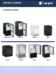
® INSTALL GUIDE ICEMAKER SERIES ADA15IM BI2115 WH95 BI98 SP18 SS1095 SS98 BI95 The Built-In Undercounter Leader Since 1962 ULINE.
1 Table of Contents Safety Precautions Safety Alert Definitions.........................................................................................................................................2 General Precautions ..............................................................................................................................................2 Inspect & Plan Product Registration ..............................................................................................................
2 Safety Precautions General Precautions IMPORTANT • PLEASE READ all instructions before installing, operating, or servicing the appliance. • Proper installation procedures must be followed when completing an installation or relocation of a unit. Consult the installation guide before any installation begins. U-Line contact information appears on the rear cover of this guide.
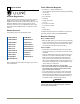
Tools / Material Required 3 Inspect & Plan • Screwdrivers — slotted and Phillips head • 1/4-inch thick door panel material and cutting tools (If installing a 1/4” Panel) • 1/4” Nut Driver Product Registration • 5/16” Nut Driver You have received a carton containing your ice maker unit with a package inside containing a Use and Care Guide, a Product Registration Card, and a water line kit. Please complete and mail the Product Registration Card or register online at www.ULineService.com.
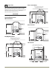
BI-98 / SS-98 Models 4 Prepare Site Filler Panel (Not Provided by U-Line) – May Be Added Above or Below Unit to Enclose for a Built-In Look Your U-Line product has been designed for either free-standing or built-in installation. When built-in, your unit does not require additional air space for top, sides or rear. However, the front grille must NOT be obstructed and clearance is required for an electrical and water connection in the rear.
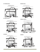
BCM95 Models SS-1095NF Models Filler Panel (Not Provided by U-Line) – May Be Added Above or Below Unit to Enclose for a Built-In Look Typical Counter Height 34-1/4" to 35-1/8" Cut-Out Height 25-1/16" Filler Panel (Not Provided by U-Line) – Needed to Attach Mounting Flange on Unit 18-1/2”” Minimum 18-1/2" Minimum See Electrical Specifications for Power Supply See Electrical Specifications for Power Supply Cut-Out Height 25-1/8” 8" Height From Floor 8" 14-1/4" 3/4” Minimum Flange Mounting Area 14-
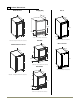
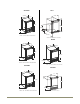
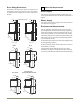
ADA15IM BI95 95TP BCM95 5 Product Dimensions ADA15IM Series BI95(B)(WH) BI2115 17” * 23”* 23-3/16" 25-1/16" 34-1/8" 32” 8-15/16” 13-15/16" 15” *Add 1-1/2” For Water Line Clearance BI95BTP *Add 3/4” To Depth For Water Line Clearance ADA15IM Stainless Series 3-13/16” 15" *Add 5/8” For Water Line Clearance BI2115 Stainless 17"* 17"* 23-1/8” 23”* 25-1/16" 25-1/16" 8 15/16” 15-1/8" 8 15/16” 34-1/8" *Add 1-1/2” For For Water Line Clearance 15-1/8" 32” *Add 1-1/2” For For Water Line Clearan
SS1095 SP18 BCM95 WH95 SS1095NF SS1095FD SP18 15-1/8" 15-15/16” 17” * 26-1/16” 18-7/8" 7 9/16”" 9” 1/2" 24-1/2" * *Add 1 1/2” For Water Line Clearance SS1095FC *Add 1-1/2” For Water Line Clearance BCM95 15-1/8” 17” * 15-1/8" 17"* 25-1/8” 25-1/8" 9” 8 15/16” *Add 1 1/2” For Water Line Clearance *Add 1-1/2” For For Water Line Clearance SS1095NF WH95TP 14” 17” * 14" 25-1/16” 17"* 25-1/8" 9” 8 15/16” *Add 1 1/2” For Water Line Clearance Product Dimensions *Add 1-1/2” For For Water Line C
Door Swing Dimensions 6 Other Site Requirements All units have a zero clearance for the door to open 90°. U-Line recommends a minimum door clearance of 2" to accommodate the handle if the unit is installed next to a wall or similar type of structure. ADA15IM Series Wall Units requires a grounded and polarized 115 VAC, 60 Hz, 15A circuit (normal household current). See Electrical Specifications on Page 14. Water Supply Wall 1/4" Min. Power Supply 2" Min.
6. Remove plastic hole plug from door handle and relocate on opposite side. See Figure 6. 7 Door Reversal Hinge BI95 & BI98 Reversing the Door Plastic Plug Hole All units may be left- or right-hand opening. Plastic Plug Hole Note: The grille should not yet be installed. If it has been installed, remove it for door reversing. Screw To reverse the door: 1. Remove top hinge from cabinet (three screws). See Figure 1. Hold door to keep it from falling. 2. Lift the door off the bottom hinge.
WH95TP, BI95BTP, BCM95 & SP18 6. Relocate plastic spacer/ bushing on bottom of door to opposite side, and place door on bottom hinge pin. See Figure 14. Clean out bushing hole in door bottom with a screwdriver if necessary. Reversing The Door All units may be left- or right-hand opening. To reverse the door: 1. Remove travel pin from cabinet (two screws). See Figure 9. Slide assembly through flange and set aside to be used later. 7.
SS1095 7. Relocate plastic spacer/bushing (Figure 24) on top and bottom of door to opposite side. Clean out bushing hole in door bottom with a screwdriver if necessary. Reversing the Door Depending upon the location of the unit, it may be desirable to change the side on which the door is mounted. To reverse the door mounting, perform the following: 1. Remove grille (one screw) (Figure 19). Mod el SS1095FC 8.
28 13. Remove all three screws on the opposite side of the hinge and carefully lift off the door latch assembly (Figure 28). 14. Place the door latch assembly on opposite side of unit (Figure 29 30 29). Be sure to tighten all three screws securely. 15. Place door on lower hinge pin. Invert and install upper hinge on door. Fasten upper hinge to unit (three screws (Figure 30). Partially tighten screws. 16. Adjust door to assure proper seal. Tighten upper and lower hinge screws securely. 17.
3. Remove the two outside screws holding door handle. Slightly separate door handle from door. 8 Door Panel Installation Door Panel Preparation BI-95, BI-2115B(WH), WH95BTP 4. Pull handle up and off. A custom door panel may be inserted into the doorframe. Custom door panels can be flat or raised, as long as the maximum panel thickness, where inserted into the door reveal (channel), is no more than 1/4" thick. For raised panels, the depth of the reveal is 1/4" on all four sides. 5.
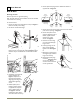
9 9 Adjust Door 10 Power Supply Electrical Specifications Checking Door Alignment The unit’s door is aligned at the factory before shipment. However, its alignment could have been disturbed during shipment. WARNING SHOCK HAZARD — Electrical Grounding Required. IMPORTANT Properly aligned, the door’s gasket should be firmly in contact with the cabinet all the way around the door (no gaps). • Never remove the round grounding prong from the plug and never use a two-prong grounding adapter.
9 11 Plumbing IMPORTANT CAUTION Plumbing installation must observe all state and local codes. All water and drain connections MUST BE made by a licensed/qualified plumbing contractor. Failure to follow recommendations and instructions may result in damage and/or harm. For units with front mounted water solenoids, route the water supply line through the unit so it does not come into contact with any internal components other than the solenoid valve. Normal operation creates some vibration.
Installation 12 Install 1. Open the water supply valve in the main water source. Leveling Information ADA15IM & BI2115 2. Plug in the powercord. It is recommended that the unit is level. 3. Gently push the unit into position. Be careful not to kink the water supply line or entangle the electrical cord. 1. Use a level to check the levelness of the unit from front to back and from side to side. Level should be placed along top edge and side edge as shown 2.
Installation Troubleshooting Q: Problem Water is leaking under the unit. A: Solution A water leak under the unit is most likely caused by a bad connection in the water supply line. Make sure the water line’s brass fitting is screwed tight to its valve and threaded correctly. Make sure that plumbers tape was NOT used; if it was remove all traces before reinstalling. BI-2115 Specific Q: Problem The door remains open unless it is pushed closed.
® INSTALLATION GUIDE SERVICE INFORMATION If you have a problem with this appliance, your use and care guide has troubleshooting information to help you quickly identify common problems and provide information on possible cause and remedy. Answers to Customers Frequently Asked Questions are available at www.u-line.com/customer/faq.cfm. You may contact U-Line directly: GENERAL INQUIRIES: SERVICE ASSISTANCE: U-Line Corporation P.O. Box 245040 Milwaukee, Wisconsin 53224-9540 U.S.A.