É c h e l o n™ P. O . B o x 2 4 5 0 4 0 Milwaukee, WI 53224-9540 ™ Phone: 414.354.0300 Fax: 414.354.7905 w w w . u - l i n e . c o m U S E R M P r i n t e d i n U . S . A .
U-LINE CORPORATION LIMITED WARRANTY U-Line Corporation warrants each U-Line product to be free from defects in materials and workmanship for a period of one year from the date of purchase; and warrants the sealed system (consisting of the compressor, the condenser, the evaporator, the hot gas bypass valve, the dryer and the connecting tubing) in each U-Line product to be free from defects in materials and workmanship for a period of five years from the date of purchase.
0-10007_Body_UM.qxd 3/21/05 1:25 PM Page 1 INTRODUCTION Congratulations on your purchase of U-Line ice making or refrigeration products. A pioneer in the field for nearly 40 years, U-Line is the world’s number one manufacturer of built-in, under-counter ice making and specialty refrigeration products. U-Line dedicates 100% of its research and development to these products. The result: U-Line technology leads the market with innovation, design, depth of product line and performance.
30-10007_Body_UM.qxd 3/21/05 1:25 PM Page 2 User’s Manual If you do not return your Warranty Registration Card, U-Line will use the date of sale to the U-Line distributor as the first date of warranty for your unit. Please also record the purchase date of your U-Line unit and your dealer’s name, address and telephone number.
30-10007_Body_UM.qxd 3/21/05 1:25 PM Page 3 SAFETY PRECAUTIONS Do not attempt to install or operate your unit until you have read the safety precautions in this manual. Safety items throughout this manual are labeled with a Danger, Warning or Caution based on the risk type. DEFINITIONS ! This is the safety alert symbol. It is used to alert you to potential personal injury hazards. Obey all safety messages that follow this symbol to avoid possible injury or death.
30-10007_Body_UM.qxd 3/21/05 1:25 PM Page 4 User’s Manual GENERAL PRECAUTIONS ! DANGER ! RISK OF CHILD ENTRAPMENT. Before you throw away your old refrigerator or freezer, take off the doors and leave shelves in place so that children may not easily climb inside. ! WARNING • Never attempt to repair or perform maintenance on the unit until the electricity has been disconnected.
30-10007_Body_UM.qxd 3/21/05 1:25 PM Page 5 INSTALLATION SITE PREPARATION 1. Position the unit on a flat, level surface, capable of supporting the entire weight of the unit. Remember the unit will be significantly heavier once it is fully loaded. 2. This unit requires grounded and polarized 115 VAC, 60Hz, 15A circuit (normal household current). It is extremely important that the unit is level. If it is not level, the ice mold will not fill evenly.
30-10007_Body_UM.qxd 3/21/05 1:25 PM Page 6 User’s Manual ! DANGER ! ELECTROCUTION HAZARD! Electrical Grounding Required. This appliance is equipped with a three-prong (grounding) polarized plug for your protection against possible shock hazards. It must be plugged into a properly grounded three-prong receptacle. • NEVER remove the round grounding prong from the plug. • NEVER use a two-prong grounding adapter. • NEVER use an extension cord to connect power to the unit.
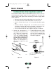
30-10007_Body_UM.qxd 9. 3/21/05 1:25 PM Page 7 Position the unit to allow free air flow through the front grille (see Figure 2). 4 3 5 2 6 OFF ON 1 7 WARMER COLDER EXHAUST INTAKE UL307 Figure 2 10. Wipe out inside of unit and ice bucket with a damp cloth.
30-10007_Body_UM.qxd 3/21/05 1:25 PM Page 8 User’s Manual CONNECTING THE WATER SUPPLY On Ice Maker models BI 2015 and Combo 2075FF, install a 1/4 inch outside diameter copper water line (not supplied with unit) from the nearest COLD water pipe. When connecting the water supply, follow these guidelines: • Review the local plumbing codes before you install the unit. • The water pressure should be between 15 and 150 psi. • Install a shut-off valve in the 1/4 inch outside diameter supply line.
30-10007_Body_UM.qxd 3. 3/21/05 1:25 PM Page 9 For recessed installations, allow extra water supply line length to provide slack for easy removal from the recessed area (see Figure 5). This will also safeguard against kinking the line. UL100 Figure 5 CAUTION If you are not intending to use the ice maker and do not connect the water supply (or turn the supply valve off), it is imperative to raise the bin arm of the ice maker (see Figure 6).
30-10007_Body_UM.qxd 3/21/05 1:25 PM Page 10 User’s Manual LEVELING THE UNIT It is important that the unit, primarily the Ice Maker models, are level. All Échelon™ Series units are equipped with adjustable feet for leveling and height adjustment (see Figures 7 & 7A). CHECK LEVEL TURN FOOT TO ADJUST UL314 UL105 Figure 7 Figure 7A REVERSING THE DOOR All U-Line units (except Stainless Steel models which must be ordered left or right hand opening) are field reversible for left or right hand opening.
30-10007_Body_UM.qxd 3/21/05 1:25 PM Page 11 3. To reverse the door: 1. Remove top hinge screw pin (7/64" Allen wrench) from cabinet (see Figure 9). Remove door by tilting forward and lifting off bottom hinge pin. Remove top hinge (3 screws), reinstall hinge screw pin, and remount on opposite side BOTTOM (see Figure 11). HINGE SCREW PIN UL313 Figure 11 4. UL310 Figure 9 2.
30-10007_Body_UM.qxd 3/21/05 1:25 PM Page 12 User’s Manual 5. Remove existing bottom hinge (3 screws) and remount on opposite side TOP. Remove top hinge screw pin. 6. With bottom of door facing up, remove pivot plate (2 screws), flip over, and remount on opposite side of door (see Figure 13). UL319A Figure 13 7. Holding door upright with top of door tilted forward, place hole of door pivot plate on bottom hinge screw pin (see Figure 14).
30-10007_Body_UM.qxd 3/21/05 1:25 PM Page 13 DOOR ADJUSTMENT Your door is aligned at the factory before shipment. Occasional re-adjustment may be necessary, especially if an Overlay Panel is installed. The following procedure will correct for up to 1/4" alignment. The door should never be flush with the top of the cabinet. Even when level, the top edge of the door will be 1/8" below the top of the cabinet (see Figure 15). To adjust : 1.
30-10007_Body_UM.qxd 3/21/05 1:25 PM Page 14 User’s Manual CUSTOM DOOR PANELS Two types of custom door panels can be installed on your U-Line unit to harmonize with or accent the surrounding decor. FULL OVERLAY DOOR PANEL A full overlay door panel completely covers the door frame and handle to give a built-in appearance. See your U-Line dealer for the optional Full Overlay Door Panel Kit which contains the Panel Preparation Document for building and installing a full overlay panel.
30-10007_Body_UM.qxd 3/21/05 1:25 PM Page 15 Install the insert as follows: ! WARNING Insert edges may be SHARP! Use care when installing. 1. Remove top hinge screw pin (7/64" Allen wrench, see Figure 17). Remove door by tilting forward and lifting off bottom hinge pin. 2. Remove two outside screws holding door handle. Slightly separate door handle from door (see Figure 18). 3. Pull door gasket out of groove (top edge of door only).
30-10007_Body_UM.qxd 3/21/05 1:25 PM Page 16 User’s Manual 6. Holding door gasket out of the way, replace handle on door making sure it is seated properly on insert and that screw holes line up. 7. Install two small screws removed in step 2. 8. Starting at the corners and working inward, push door gasket into place on door. 9. Place door on bottom hinge pin and install upper hinge screw. BUILT-IN INSTALLATION Your U-Line product has been designed for either free-standing or builtin installation.
30-10007_Body_UM.qxd 3/21/05 1:25 PM Page 17 CONTROL SETTINGS - COMBO/ICE MAKER TEMPERATURE CONTROL KNOB Models BI 2015 and 2075FF are turned ON with the ON/OFF switch recessed in the front grille (see Figure 21). In these units, the control dial is used only for temperature control. 4 3 5 1 7 WARMER COLDER 2 6 OFF ON ON/OFF SWITCH UL316B Figure 21 1. Plug the appliance cord into a 115V polarized and grounded electrical outlet. 2. All units are shipped in the ON position. 3.
30-10007_Body_UM.qxd 3/21/05 1:25 PM Page 18 User’s Manual NORMAL OPERATION On units with refrigerator sections, the unit has been designed to achieve a fresh food temperature of approximately 38°F. Those units with a freezer section are designed to have a freezer temperature of approximately 0°F. On units with ice makers, when the ice bucket is full, the ice making mechanism will shut off. However, the refrigeration system will continue to cool and maintain the cube supply.
30-10007_Body_UM.qxd 3/21/05 1:25 PM Page 19 The ice bin door must be fully closed with the door lip inside the ice bucket. Frost free models: Do not place any objects over air inlet or outlet in freezer section. For frost free models: Light frosting may occur in high humidity conditions or if the ice bucket is not pushed in completely. BI 2015 is not frost free and must be defrosted periodically. Refer to MAINTENANCE. Do not place cans or bottles so they are touching the back of the unit.
30-10007_Body_UM.qxd 3/21/05 1:25 PM Page 20 User’s Manual OUTDOOR & MARINE USE Many U-Line models are designed to operate in harsh outdoor/marine environments. Special considerations include the following: • For best performance, keep the unit out of direct sunlight. • On Ice Maker models, turn the unit OFF and dispose of any ice cubes if the unit will not be used for 5 days or more. Prop door open to allow for air circulation and prevent mold and mildew.
30-10007_Body_UM.qxd 3/21/05 1:25 PM Page 21 3. Turn the adjusting screw toward the minus (–) sign (clockwise) for smaller cubes or toward the plus (+) sign (counterclockwise) for larger cubes. 4. Install the ice maker assembly cover. MAINTENANCE Periodic cleaning and proper maintenance will ensure efficiency, top performance, and long life. The maintenance intervals listed are based on normal conditions.
30-10007_Body_UM.qxd 3/21/05 1:25 PM Page 22 User’s Manual • USE OF ABRASIVE PADS SUCH AS SCOTCHBRITE WILL CAUSE THE GRAINING IN THE STAINLESS TO BECOME BLURRED. • Rust that is allowed to linger can penetrate into the surface of the stainless steel and become impossible to remove. CAUTION Stainless steel models exposed to chlorine gas and moisture, such as areas with spas or swimming pools, may have some discoloration of the stainless steel. Discoloration from chlorine gas is normal.
30-10007_Body_UM.qxd 3/21/05 1:25 PM Page 23 ! WARNING • DO NOT use solvent cleaning agents or abrasives on the interior. These cleansers may transmit taste to the ice cubes, or damage or discolor the interior. CONDENSER CLEANING - EVERY 3 MONTHS ! WARNING Disconnect electric power to the unit before cleaning the condenser. To remove and replace the grille for access to the condenser fins follow this procedure: 4 3 5 2 6 OFF ON 1 7 WARMER COLDER EXHAUST INTAKE Figure 27 1.
30-10007_Body_UM.qxd 3/21/05 1:25 PM Page 24 User’s Manual 3. Clean the condenser coil using a brush or vacuum cleaner. Do not touch. 4. Position the grille to align the screw holes with the cabinet. 5. Insert the grille screws and tighten being careful not to overtighten. 6. Install the control knob by aligning the flat of the control knob with the flat on the shaft. Push firmly. INLET SCREEN CLEANING The solenoid valve inlet screen must be cleaned at least once each year as follows: 1.
30-10007_Body_UM.qxd 3/21/05 1:25 PM Page 25 GLASS SHELF REMOVAL/INSTALLATION Removal (see Figure 29) 1. Pull shelf out about 6" until back of shelf clears the “hump” on the right hand side. 2. Tilt right hand edge of shelf up. 3. Remove shelf from unit by pulling out. 3 1 2 Adjustment/Installation Figure 29 UL301 1. To move to a different position in the unit, insert shelf at an angle, approximately 15-20°, over the rib in the side of the unit where you want to place the shelf.
30-10007_Body_UM.qxd 3/21/05 1:25 PM Page 26 User’s Manual CRISPER ! CAUTION Slowly pull out the crisper. If it is pulled out too far, it could come out all the way and possibly cause damage or injury. Combo 2075FF, 2075R and 2075RF models have a crisper for storage. Grasp the crisper handle and pull out to access the contents (see Figure 31). The crisper may be completely removed for cleaning. UL304 Figure 31 LIGHT BULB REPLACEMENT Light bulb replacement Échelon™ series is simple. 1.
30-10007_Body_UM.qxd 3/21/05 1:25 PM Page 27 DEFROSTING ! WARNING DO NOT use any type of electrical heating device, ice pick, knife, or other sharp instrument to defrost. Doing so may cause personal injury or damage the inner lining or refrigeration system and void the warranty. BI 2015 is a manual defrost model and should be defrosted approximately every 8 weeks. However, this interval may not be adequate in periods of high humidity or heavy usage.
-10007_Body_UM.qxd 3/21/05 1:25 PM Page 28 User’s Manual CONDENSER OFF ON 4 3 5 6 2 1 7 WARMER COLDER UL317 Figure 33 Remove the control knob by grasping the knob and pulling straight off (see Figure 33). STORAGE If the unit is to be stored or not used for extended periods, it will be necessary to drain the system of water. 1. Shut off water supply at the main water source. 2. Disconnect the water supply line from the solenoid valve. 3.
30-10007_Body_UM.qxd 3/21/05 1:25 PM Page 29 TROUBLESHOOTING BEFORE CALLING FOR SERVICE If the unit appears to be malfunctioning, read through NORMAL OPERATION first. If the problem persists, check the TROUBLESHOOTING GUIDE. Locate the problem in the guide and refer to the cause and its remedy before calling for service. The problem could be something very simple which can be solved without a service call.
30-10007_Body_UM.qxd 3/21/05 1:25 PM Page 30 User’s Manual Problem The unit frosts up. Water is leaking out the back of the unit. Ice cubes sticking together. Noise during operation. No ice. Possible Cause Unit is manual defrost model. High ambient temperatures or humidity. Water supply connection leaking. Infrequent use of cubes. Copper water supply tubing contacting internal components. Certain sounds are normal. Bin arm locked in upright position. No water to unit. Not enough ice.
30-10007_Body_UM.qxd 3/21/05 1:25 PM Page 31 IF SERVICE IS REQUIRED If the need for service arises, contact the dealer from whom the unit was purchased. State the Model Number and Serial Number and explain the problem. The Model and Serial Number plate is located inside unit at upper right hand corner. If you do not know the name of the selling dealer or local service company, you can check on-line at www.U-LineService.com. REPLACEMENT PARTS Use only genuine U-Line replacement parts.
30-10007_Body_UM.
U-LINE CORPORATION LIMITED WARRANTY U-Line Corporation warrants each U-Line product to be free from defects in materials and workmanship for a period of one year from the date of purchase; and warrants the sealed system (consisting of the compressor, the condenser, the evaporator, the hot gas bypass valve, the dryer and the connecting tubing) in each U-Line product to be free from defects in materials and workmanship for a period of five years from the date of purchase.
É c h e l o n™ P. O . B o x 2 4 5 0 4 0 Milwaukee, WI 53224-9540 ™ Phone: 414.354.0300 Fax: 414.354.7905 w w w . u - l i n e . c o m U S E R M P r i n t e d i n U . S . A . P / N 3 0 - 1 0 0 0 7 ( R e v .