Under the Counter Ice Maker Service Manual Models: EI15IM55GS, E15IM60GSS, and E15IM60GPS 5995504544 January 2008
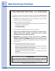
Safe Servicing Practices SAFE SERVICING PRACTICES - ALL APPLIANCES To avoid personal injury and/or property damage, it is important that Safe Servicing Practices be observed. The following are some limited examples of safe practices: 1. DO NOT attempt a product repair if you have any doubts as to your ability to complete it in a safe and satisfactory manner. 2.
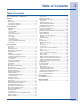
Table of Contents Table of contents Safe Servicing Practices - All Appliances........................ 2 Installation Leveling...................................................................................4 Adjusting Door.........................................................................4 Checking Door Alignment . ...................................................4 Adjusting Door Alignment.....................................................5 General Instructions Keypad Options....................
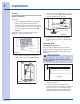
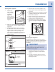
Installation Leveling It is extremely important that the unit is level for maximum protection. 2. If the unit is not level, adjust the feet on the corner as necessary. See Figure 3. Rotating the feet clockwise raises the unit. If it is not: • Doors and/or drawers will not work properly. • Uneven sized cubes will be formed. Ice production will be reduced and water spilling into the storage area can occur, causing the ice in the bin to melt prematurely. See Figure1.
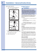
1" ± 1/32" 1" ± 1/32" ULIN_0310_A Installation Figure 6 ULIN_0295_A Adjusting Door Alignment 1. Remove top hinge screw pin using a Phillips screwdriver (Figure 7). Remove door by tilting forward and lifting off bottom hinge pin. oor to the top edge of Adjusting Door Alignment d parallel to the top of ly. If it is not, note 1 Remove top nge needs to be moved Figure 5 hinge screw pin ing procedure. 4 Mount the door to recheck alignment and repeat steps 2 and 3 if further adjustment is necessary.
Installation / General Instructions Adjusting Door Alignment 7 Adjust Drawer 1. Loosen (do not remove) top and bottom hinge screws Adjusting Alignment Adjusting Door Alignment (FigureDoor 11 and Figure 12). Loosen (do remove) not remove) top bottom and bottom 1.1.Loosen (do not top and hinge screws hinge screws (Figures 9 and 10). (Figure 11 and Figure 12). Keypad Options 7 Adjust Drawer Alignment Checking Drawer WARNING Checking Drawer Alignment shipment.
General Instructions the control, touch any key and the degree symbol will begin to flash To exit this mode: If using software version 2.8, this mode will exit automatically when the unit is unplugged. If usong software version 2.9, this mode needs to be exited by the same key combination as used to enter the mode. Service Mode Forced Defrost This will allow the unit to defrost quickly. For R and WC units, this is just an off cycle.
Service Information Service Menu Enter the Service Menu by holding UP arrow and pressing LIGHT key three times. Select option 1 to 27 with the up and down arrows. To enter the option, press LIGHT key. When entering Service Mode all other modes are cancelled and the unit will stop operating. When exiting the Service Mode, the unit will begin to operate normally. However, the four minute compressor off cycle still applies.
Service Information Quick Reference Card E9 Thermister 4 open or shorted. E11 EE Memory error. 1. 2. 3. 4. 5. Model Plug in unit. The display may show a SP or --, either is OK. Install a jumper on J3. Hold down warmer, colder,and light button until display shows model numberand main board beeps. Use warmer/colder to select new model number. P1 Pump circuit open.
Toggle Lights Adjust Set-point View Actual Temperature (T1) View Actual Temperature (T2-T4) Toggle F - C Toggle Showroom Mode Service Mode Display Toggle Blackout Mode Clean Cycle Icemaker Off Mode Forced Harvest Forced Refrigerator Defrost Ice Thickness Adjustment Temporary Shutdown (Office Mode) Relay Status Change Model Number (with jumper) 2 3 4 5 6 7 8 9 10 11 12 14 15 16 17 18 19 Hold Hold Hold Hold Hold Hold Hold Hold Hold 5 Seconds Hold 5 Seconds Hold 10 S
Service Information Keypad Options WARNING Electrocution can cause death or serious injury. Burns from hot or cold surfaces can cause serious injuty. Take precautions when servicing this unit. • Disconnect the power source. • Do not stand in standing water when working around electrical appliances. • Make sure the surfaces you touch are not hot or cold. • Do not touch a bare circuit board unless you are wearing an anti-static wriststrap that is grounded to an electrical ground or grounded water pipe.
Service Information Blackout / Sabbath Mode This mode allows for observation of holidays on which lights cannot be activated. Hold the LIGHT key for 10 seconds until the °F starts flashing. When released, the unit will beep once and the display and cabinet light will shut off. It will stay off for 36 hours, at which time it will automatically turn back on. If desired, you can manually cancel this mode by touching the LIGHT key. Release and the unit will automatically start normal operation.
Error Codes Service Information E1 Thermistor 1 is open. E2 Thermistor 1 is shorted. E3 Main door or bottom drawer is open longer than 20 minutes. Error Codes E4 Compressor had 100% runtime between two defrost E1 Thermostor 1 is open. cycles. Thermistor 1 isofshorted. E5E2Thermistor 1 out range + 10°F for more than 12 hours. E3 Main door or bottom drawer is open longer than 20 minutes. E6E4Thermistor 1 outhas of range for more thantwo 12 defrost cycles. Compressor 100%-10°F runtime between hours.
Thermistor Types Type 1 (Black) Service Information Resistance at 77°F = 10,000 Ohms ± 5% Operating range is 185,000 to 650 Ohms. Resistance goes down as temperature increases. Type 1 does not need to be calibrated and can be changed without changing other Thermistor Types wires or board. Type 1 (Black) Type 2 (White) Resistance at 77°F = 10,000 ohms ± 5% Resistance at 77°F = 5,000 Ohms ± 5% Type 2 (White) Operating rangeis is 185,000 to 650 ohms. Operating range 180,000 to 550 Ohms.
Service Information Filter-Drier Installation Any time the sealed system is opened and the refrigerant charge is removed, the liquid line filterdrier must be replaced and the system thoroughly evacuated before recharging. CAUTION DO NOT unbraze the old filter-drier from the system. This will vaporize and drive moisture from the desiccant back into the system. The old filter-drier should be cut out of the system.
Service Information Equipment Needed for Evacuation & Recharging: • Heated charging cylinder • Standard 3-port manifold gauge set: - 4 charging hoses - Tee fitting with valve core stem removed (Robinair No. 40396) - Hand shut-off valve (Robinair No.40380) • Two stage vacuum pump • Process tube adapter kit (Robinair No.
Service Information 5. 6. 7. Close hand shut-off valve to vacuum pump. Watch compound gauge for several minutes. If reading rises, there is a leak in the system, go to step 6. If no leak is indicated, stop vacuum pump. System is now ready for charging. If a leak is indicated, stop vacuum pump and introduce a small charge of refrigerant into system by cracking valve on bottom of charging cylinder until system is pressurized to 40 or 50 lbs psig. Leak test low-side. Close compound gauge.
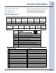
Service Information Evacuating and Recharging Connections Hot Tube Evaporator Compound Gauge Gauge Manifold Filter Drier Pressure Gauge T-Fitting Process Tube Adapters Heated Charging Cylinder Compressor Condenser 2 Stage Vacuum Pump
Service Information NOTicE Instructions given here are furnished as a guide. Persons attempting to use these instructions to make repairs to the sealed refrigeration system should have a working knowledge of refrigeration and previous training on sealed system repair. Verify Refrigerant Type In The System CAUTION R-134a and R-12 are completely incompatible. Before starting any sealed system repair, it is extremely important to check serial plate of product to verify the type of refrigerant in the system.
Service Information At the earliest stage of development work on R-134a, tests were carried out on a different type of synthetic oil known as Poly-Alkaline Glycol (PAG). This oil is also used in certain air conditioning systems for cars. PAG and Ester oil DO NOT mix with one another. Service equipment used for R-134a / Ester oil must not come into contact with PAG. Water In The Refrigeration System To achieve the required 29.
Service Information CAUTION If you use a vacuum pump with mineral oil to evacuate an R-134a system, it is ABSOLUTELY ESSENTIAL to have a shut-off valve between pump and your manifold gauge set as shown in Figure E2. The hand valve must be closed during all times when vacuum pump is not operating. This will prevent migration of mineral oil vapor into R134a/Ester oil system. If vacuum pump should stop during evacuation for any reason, the hand pump shut-off valve must be closed immediately.
Service Information HFC-134a, CFC-12 Pressure Temperature Chart °F °C HFC-134a CFC-12 °F °C HFC-134a CFC-12 -60 -51.1 21.8* 19.0* 55 12.8 51.1 52.0 -55 -48.3 20.4* 17.3* 60 15.6 57.3 57.7 -50 -45.6 18.7* 15.4* 65 18.3 63.9 63.8 -45 -42.8 16.9* 13.3* 70 21.1 70.9 70.2 -40 -40.0 14.8* 11.0* 75 23.9 78.4 77.0 -35 -37.2 12.5* 8.4* 80 26.7 86.4 84.2 -30 -34.4 9.8* 5.5* 85 29.4 94.9 91.8 -25 -31.7 6.9* 2.3* 90 32.2 103.9 99.8 -20 -28.
Service Information Inhalation Toxicity Spills or Leaks HFC-134a poses no acute or chronic hazard when it is handled in accordance with DuPont recommendations and when exposures are maintained at or below the DuPont Acceptable Exposure Limit (AEL) of 1,000 ppm (8 and 12 hour Time-Weighted Average or TWA). If a large release of vapor occurs, such as from a large spill or leak, the vapors may concentrate near the floor or low spots and displace the oxygen available for breathing, causing suffocation.
Service Information Always wear protective clothing when there is a risk of exposure to liquid HFC-134a. Where splashing is possible, always wear eye protection and a face shield. Combustibility of HFC-134a HFC-134a is nonflammable at ambient temperatures and atmospheric pressure. However, tests have shown HFC-134a to be combustible at pressures as low as 5.5 psig (139.3 kPa absolute) at 177°C (350°F) when mixed with air at concentrations generally greater than 60% volume air.
Service Information Ice Cube Thickness Adjustment Interval - As Required Ice thickness adjustments are made using the control panel as follows: 1. To enter the thickness adjustment mode: a. Touch and hold the UP ARROW button. b. Touch and release the DOWN ARROW button three times, then release the UP ARROW button. The ice cube thickness control is factory set for best overall performance.
Service Information cations Operating Environmental/Climate Control Requirements Model EI151M55GS Many product models are designed to operate in harsh outdoor/marine environments. Speial considerations include the following: Hours between Defrost Time (Runtime): 6 Length/min: 90 Stop Point: 42° Defrost Information • The units are desidned to operate between Compressor / Coil Specifications 50°F (10°C) and 110°F (40°C).
Service Information Model CLR2160 Operation HIGH PRESSURE LOWPRESSURE TRANSITIONAL PRESSURE IN CAPILLARY TUBE H L C L L ICEMAKER EVAPORATOR 2276 C R4: WATER SUPPLY L C R5: WATER CIRCULATION PUMP C L R4: HOT GAS BYPASS VALVE L H H R1: CONDENSER FAN C R3: COMPRESSOR C C CONDENSER RELAY R1 R3 FUNCTION FAN COMP Mode 1: ON Ice Making Mode 2: ON Ice Harvest Mode 3: OFF Off Mode 4: OFF Cleaning Mode 5: OFF Water Fill & Initial Start-Up * Normal Start-Up lasts 3 minutes Note: R2, R6 and R7 n
Service Information Upon initial startup, this unit will enter mode number 5 which is a three-minute water fill regardless of the thermistor temperatures. This only occurs when the intial startup is caused by a power-up of the main board. Following the three-minute water fill, the unit moves into mode 1 which is the freezing mode. In this mode the water is pumped from the sump trough over the ice maker grid by the circulation pump.
Service Information Model CLR2160 WARMER and COLDER for five seconds. We’ll assume the display showed 38°F for this example. Go to service mode #24 and adjust the setting to that number. This will allow the bin to shut off at this ice level. This temperature needs to be checked after the door has been closed for at least 10 minutes in order for the thermistor temperature to stabilize. Poor ice quality Too little ice A defect in the drain from the unit will cause water to stop draining from the unit.
Service Information Model CLR2160 Wiring Diagram ULIN_0262_A Ice Production Rates Ambient Temp/Water Temp °F Approximate Ice Production (lbs/day) 50/50 60 60/50 60 70/50 58 80/50 54 90/70 47 100/70 40 NOTE: These characteristics will vary depending on operating conditions, condenser cleanliness, installation and application.
Service Information Model CLR2160 Prepare Plumbing Gravity Drain CAUTION Plumbing installation must observe all state and local codes. All water and drain connections MUST BE made by a licensed/qualified plumbing contractor. Failure to follow recommendations and instructions may result in damage and/or harm. Waste Shut-Off Valve Drain Connection Cold Water Hot Water IMPORTANT Drain can NOT be located directly below unit. Unit has a solid base that will not allow unit to drain below itself.
Service Information Model CLR2160 Disposal Assembly Screws Back Panel Air Gap (Optional Hook-Up) Waste Hot Water Cold Water Grommet Shut-Off Valve ULIN_0572_A Drain Fitting Power Cord Figure 5 Water Connection ULIN_0574_A Figure 7 3. Remove 12 screws and back panel. Spigot Assembly WARNING Air Gap (Optional Hook-Up) Waste Shut-Off Valve Hot Water Cold Water Back panel serves as a guard.
Model CLR2160 9. Unplug unit power cord from electrical outlet. 10. Reinstall back panel. To connect to drain: 1. Attach the 5/8" ID drain connection on the back of the unit to a 5/8" OD rigid tube, using a worm clamp. 2. Attach the other end of the rigid tube to your 5/8" ID drain line with a worm clamp. 3. Insulate the drain line, if necessary, to prevent condensation.
Service Information Model CLR2160 Drain Fitting from Back of Unit 9/16" Wrench 1/4" Copper Water Supply Line 5/8" x 5/8" Barb Connector Worm Clamps Drain Line 7/16" Wrench From Water Supply to Ice Maker ULIN_S_0168_A ULIN_S_0166b2_A Figure 10 3. Your U-Line icemaker requires a drain connection. This unit can be purchased with or without a factoryinstalled drain pump.
Service Information Model CLR2160 front to back. For disposal connections an optional adapter may be required (included with the kit) to adapt from the 7/8" connection. 11. For the gravity/floor drain or the standpipe drains it is important to secure the drain tubing to those items to prevent it from coming loose. For the disposal or Y-branch tailpiece connections press the drain tube over the barbed end on the connector.
Service Information Model CLR2160 Self-Cleaning Cycle Instructions To maintain operational efficiency, clean unit every six months. (Depending on water conditions, more or less frequent cleaning may be necessary.) If the ice maker requires more frequent cleaning, consult a qualified plumber to test the water quality and recommend appropriate treatment. Use only U-Line Ice Machine Cleaner (P/N 41978). 1 CAUTION Use U-Line Iceice Machine Cleaner 41978).
Model CLR2160 Model CLR2160 Parts Information 37 8 Parts Section 8 Parts Section EI151M55GS Parts Section CLR2160 CLR2160 7 7 6 6 3 3 2 2 4 4 11 11 8 5 Figure 21 Item 2 3 4 5 6 7 8 11 Item 8 5 Figure 21 ULIN_S_0047_A ULIN_S_0047_A Description Description Figure 2 INTERIOR, CLR2160 INTERIOR, CLR2160 24 3 HINGE COMP HINGE COMP 25 4 DOOR COMPONENTS DOOR COMPONENTS 25 5 BASE ASSY, CLR2160 BASE ASSY, CLR2160 26 6 CONTROL COMPONENTS CONTROL COMPONENTS 22 7 BACK PANEL, CLR2160 BACK PANEL, CLR21
Parts Information Model CLR2160 1 2 3 6 4 5 7 8 9 10 11 Model CLR2 ULIN_S_0032b_C Figure 22 Item 48 Description Part Number 1 THERMISTOR (quick connect white) 68073 2 CIRCUIT BOARD ASSEMBLY 68072-S 3 SWITCH JUMPER (included with 68072-S) 68080 4 CIRCUIT BOARD SUPPORTS (included with 68072-S) 41992 5 CIRCUIT BOARD SUPPORT (included with 68072-S) 41993 6 LIQUID LINE THERMISTOR (quick connect black) 68076 7 BASEPLATE, LINER 26086 8 DISPLAY ASSY, ECHELON 68074 9 DISPL
Parts Information Model CLR2160 Model CLR2160 9 1 9 1 2 2 8 8 6 6 7 7 4 4 5 3 ULIN_S_0085c_A 3 Item 5 Figure 23 ULIN_S_0085c_A Figure 23 Description Part Number 1 BACK PANELItem 2 BACK PANEL SCREWS 1 BACK PANEL 41342 11964-02 3 SOLID HOLE COVER 2 BACK PANEL SCREWS 42125 41342 4 PERFORATED HOLE COVER 3 SOLID HOLE COVER N/A 42125 5 BLACK BUSHING 4 41955 N/A 6 DRYER (included 2269-S) 5 with BLACK BUSHING 2850 41955 7 PROCESS TUBE6(included with 2269-S) with 2269-S) DRYER
Parts Information Model CLR2160 Model CLR2160 4 11 43 8 11 3 8 5 5 2 2 9 10 6 1 10 9 6 1 7 7 ULIN_S_0075_A Figure 24 ULIN_S_0075_A Item 1 2 3 4 5 6 7 8 9 10 11 Description STAND PIPE Item Description FRONT COVER 1 STAND PIPE WELL NUT (included with 31613-S) 2 FRONT COVER PRE-FORMED WHITE TUBE 3 WELL NUT (included with 31613-S) CIRCULATION PUMP COVER 4 PRE-FORMED WHITE TUBE ICE SCOOP HANGER 5 CIRCULATION PUMP COVER WATER TROUGH WITH DRAIN TUBE 6 ICE SCOOP HANGER WATER DISPERSION RECEPTA
Parts Information Model CLR2160 9 13 2 12 3 4 14 11 Accessory only This is not a Replaceable part 14 1 12 10 13 6 7 5 8 17 Model CLR2160 16 Item 15 Part Number Description Figure 25 Black 1 DOOR ASSEMBLY 2 3 Right Hand White ULIN_S_0049a_A Stainless Steel 80-17071-01 80-17071-02 NAMEPLATE 23025 23025 HANDLE ASSEMBLY 26071-01-S 26071-02-S N/A Left Hand 80-17071-03 80-17071-13 23025 4 52 HOLE PLUG (included with handle assembly) 42173-BLK 42173-NAT N/A 5 DOOR GASKET
Parts Information Model CLR2160 1 2 5 3 6 7 4 10 11 12 8 9 13 14 17 15 18 16 ULIN_S_0064b_A Figure 26 54
Model CLR2160 43 Parts Information Model CLR2160 18 18 ULIN-P60-00_A Figure 27 ULIN-P60-00_A Figure 26 Figure 27 Figure 26 Item Description Part Number 1 COMPRESSOR EMY70HER 2 PROCESS TUBE (included with 70081-S) 1 COMPRESSOR EMY70HER 2819 3 DRYER (included2withPROCESS 70081-S)TUBE (included with 70081-S) 2693 2819 4 GROMMET (included with 70081-S) 3 DRYER (included with 70081-S) 31021 2693 5 4 GROMMET (included with 70081-S) OVERLOAD (included with 70081-S) 71027 31021 6 RELAY (
Parts Information Model CLR2160 Model CLR2160 1 1 3 4 3 4 5 5 9 9 7 2 7 8 2 8 6 6 ULIN_S_0077_A Figure 28 ULIN_S_0077_A Item 1 2 3 4 5 6 7 8 9 Description EVAPORATOR ASSEMBLY Item Description HEAT EXCHANGER (included with 2276-S) 1 EVAPORATOR ASSEMBLY PROCESS TUBE (included with 2276-S) 2 HEAT EXCHANGER (included with 2276-S) BYPASS TUBE (included with 2276-S) 3 PROCESS TUBE (included with 2276-S) SUCTION TUBE (included with 2276-S) 4 BYPASS TUBE (included with 2276-S) DRYER (included with 22
Customer Call Guide The warranty does not cover customer education calls. It has been reported that as high as 50% of all service calls performed are customer education calls. The following guide that been developed to help answer frequently asked questions. It can be used by persons scheduling service calls.
Customer Call Guide Concern When I turn the unit on, all I get is water fill. Response Ounce the unit is turned on, there will be a three minute water fill. This ensures a fresh batch of water has filled the trough. If water flows more than three minutes, a service call will be required. My ice does not come out in a When the ice is made, a small hole or “dimple” will appear on the front perfect cube shape. or top of the cube.