π H-1027, H-1028 H-3064 PNUEMATIC STICK STAPLER Pour le français, consulter les pages 12-22. 1-800-295-5510 uline.com stapler specifications Dimensions: L x H x W 13.5 x 8.75 x 6" Weight (Without Fasteners) 6 lb. Compressed Air: Maximum psi: 110 psi Recommended Operating Pressure: 71–100 psi Air Consumption: 2.
safety instructions general safety Lubrication & Maintenance 1. Read the manual and understand all safety instructions before operating the stapler. If you have questions, contact Uline at 1-800-295-5510. 1. Lubricate the stapler prior to initial operation. 2. Never use flammable gases as a power source for the stapler. Only use filtered, compressed air. 3. Never use gasoline or other flammable liquids to clean the stapler. Vapors left on the stapler could ignite and cause the stapler to explode. 4.
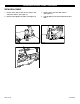
safety instructions continued Loading the Stapler 1. Disconnect the air supply. 2. Pull the pusher back until it stops on pusher pivots. Rotate pusher to position. (See Figure 1) 3. Insert 2 sticks of appropriate staples into the magazine. Let the sticks slide forward to the front of the magazine. (See Figure 2) 4. Pull the pusher back to an upright position and gently let the pusher slide forward against the staples.
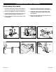
safety instructions continued Clinch Adjustment Use 2.5 mm Allen wrench and turn collar through window clockwise to tighten clinch. (See Figure 6) Loosen Tight Medium Tighten Loose Figure 6 Depth Adjustment 1. Loosen front screw with a 6 mm Allen wrench. (See Figure 7) 2. Push the body up and adjust to the desired depth. (See Figure 8) Figure 7 3. When the top edge of the adjustment plate is at its highest setting the teeth are at their shallowest penetration. (See Figure 9) 4. If set at No.
operating instructions Warning 1. Protect your eyes and ears. a. Wear safety glasses with side shields b. Wear hearing protection. c. Ensure that anyone in the vicinity wears safety protection. 2. To prevent accidental injuries, never place a hand or any other body part in the staple clinching area or adjustment window. 3. Never point the stapler towards you or anyone else. 4. Always handle the stapler with care. Never pull the trigger unless stapler is ready for operation. 5.
OPerating instructions continued Clearing a Jam 3. Insert needle nose pliers or screwdriver to clear jam. (See Figure 12) 1. Disconnect air supply. 2. Pull pusher back and rotate to a locked position. (See Figure 11) Figure 11 4. Slowly release pusher back to position. Figure 12 Warning Stop using the stapler immediately if any of the following problems occur. Serious personal injury could occur. Any repairs or replacements must be done by a qualified person or authorized service center only.
OPerating instructions continued Teeth Replacement 1. Loosen screws and nut with an 8 mm wrench and 4 mm Allen wrench. (See Figure 13) 3. Loosen screws with 3 mm Allen wrench. (See Figure 15) 2. Remove the magazine assembly. (See Figure 14) 4. Change teeth one at a time to prevent reverse teeth.
OPerating instructions continued Driver Replacement 1. Disconnect the air supply. 2. Loosen screw and nut with a 8 mm spanner wrench and a 4 mm Allen wrench. (See Figure 16) 3. Remove the magazine assembly. (See Figure 17) 4. Loosen the set screw with a 3 mm Allen wrench to unlock the adjusting rod. 5. Slide the linkage mechanism and adjusting rod simultaneously from the collar. (See Figure 18) 6. Loosen the screws with a 3 mm Allen wrench. (See Figure 19) 7.
OPerating instructions continued Pusher Spring Replacement 1. Loosen the screws and nut with a 8 mm spanner wrench and a 4 mm Allen wrench. (See Figure 21) 5. Loosen the screw and nut with a 2.5 mm Allen wrench and 7 mm socket wrench. (See Figure 24) 2. Remove the magazine assembly. (See Figure 22) 6. Loosen the rod with a 6 mm offset wrench and remove the pusher guides. Remove the pusher. (See Figure 25) 3. Pull the pusher back until it stops on the rod, then rotate the pusher to position.
OPerating instructions continued Valve AND Tube O-Ring Replacement 1. Loosen screws with a flat screwdriver. (See Figure 27) 2. Remove spring with needle nose pliers. (See Figure 28) Figure 27 3. Remove C-ring with C-ring pliers. (See Figure 29) 4. Remove valve and tube with needle nose pliers.
OPerating instructions continued Piston Replacement 1. Remove screws and nut with 8 mm spanner wrench and 4 mm Allen wrench. (See Figure 31) 6. Loosen screw with a 3 mm Allen wrench and remove the block through the window. 2. Remove magazine assembly. (See Figure 32) 7. Loosen screws with a 3 mm Allen wrench and remove the cap. (See Figure 34) 3. Loosen set screw with a 3 mm Allen wrench to unlock the adjusting rod. 4. Slide linkage mechanism and adjusting rod simultaneously from collar. 8.
π H-1027, H-1028 H-3064 AGRAFEUSE PNEUMATIQUE À AGRAFES EN BANDE 1-800-295-5510 uline.ca SPÉCIFICATIONS DE L'AGRAFEUSE Dimensions : long. x haut. x larg.
CONSIGNES DE SÉCURITÉ SÉCURITÉ GÉNÉRALE Lubrification et entretien 1. Lisez ce manuel et assurez-vous de comprendre toutes les consignes de sécurité avant d'utiliser l'agrafeuse. Pour toute question, communiquez avec Uline au 1 800 295-5510. 1. Lubrifiez l'agrafeuse avant son utilisation initiale. 2. N'alimentez jamais l'agrafeuse avec des gaz inflammables. Utilisez uniquement de l'air comprimé filtré. 3.
CONSIGNES DE SÉCURITÉ suite CHARGEMENT DE L'AGRAFEUSE 1. Déconnectez l'alimentation en air. 2. Tirez le pousseur vers l'arrière jusqu'à ce qu'il bute sur les pivots de pousseur. Tournez le pousseur en position. (Voir Figure 1) 4. Ramenez le pousseur à la position horizontale et laissez-le doucement glisser contre les agrafes. Ne laissez pas le pousseur heurter les agrafes à vitesse élevée, car cela pourrait déformer les agrafes et endommager l'agrafeuse. 3.
CONSIGNES DE SÉCURITÉ suite Réglage de la fermeture Serrez la fermeture en tournant le collet dans le sens horaire à travers la fenêtre à l'aide d'une clé Allen 2,5 mm. (Voir Figure 6) Desserrer Serrée Moyenne Serrer Lâche Figure 6 Réglage de la profondeur 1. Desserrez la vis avant à l'aide d'une clé Allen 6 mm. (Voir Figure 7) 2. Poussez le corps vers le haut et réglez l'ensemble à la profondeur voulue. (Voir Figure 8) 3.
INSTRUCTIONS D'UTILISATION AVERTISSEMENT 1. Protégez vos yeux et vos oreilles. a. Portez des lunettes de sécurité avec écrans latéraux. b. Portez un dispositif de protection de l'ouïe. c. Assurez-vous que toute personne dans la zone immédiate porte un dispositif de protection. 2. Ne placez pas votre main ou toute autre partie de votre corps dans la zone de fermeture d'agrafe ou dans la fenêtre de réglage lors de la connexion ou la déconnexion de l'air comprimé. 3.
INSTRUCTIONS D'UTILISATION suite DÉGAGEMENT D'UNE OBSTRUCTION 3. Insérez une pince à bec effilé ou un tournevis afin de dégager l'obstruction. (Voir Figure 12) 1. Déconnectez l'alimentation en air. 2. Tirez le pousseur vers l'arrière et tournez-le en position verrouillée. (Voir Figure 11) 4. Ramenez délicatement le pousseur en position. Figure 11 Figure 12 AVERTISSEMENT Cessez immédiatement d'utiliser l'agrafeuse si l'un ou l'autre des problèmes suivants se produit.
INSTRUCTIONS D'UTILISATION suite REMPLACEMENT DE DENTS 1. Desserrez les vis et l'écrou à l'aide d'une clé 8 mm et d'une clé Allen 4 mm. (Voir Figure 13) 3. Desserrez les vis à l'aide d'une clé Allen 3 mm. (Voir Figure 15) 2. Retirez le magasin. (Voir Figure 14) 4. Remplacez les dents une à la fois afin d'éviter de les inverser.
INSTRUCTIONS D'UTILISATION suite Remplacement de la plaque de poussée 1. Déconnectez l'alimentation en air. 2. Desserrez les vis et l'écrou à l'aide d'une clé 8 mm et d'une clé Allen 4 mm. (Voir Figure 16) 3. Retirez le magasin. (Voir Figure 17) 4. Pour déverrouiller la tige de réglage, desserrez la vis de réglage à l'aide d'une clé Allen 3 mm. 5. Glissez simultanément les liens et la tige de réglage à l'écart du collet. (Voir Figure 18) 6. Desserrez les vis à l'aide d'une clé Allen 3 mm.
INSTRUCTIONS D'UTILISATION suite REMPLACEMENT DU RESSORT DE POUSSEUR 1. Desserrez les vis et l'écrou à l'aide d'une clé 8 mm et d'une clé Allen 4 mm. (Voir Figure 21) 5. Desserrez les vis et l'écrou à l'aide d'une clé 2,5 mm et d'une clé Allen 7 mm. (Voir Figure 24) 2. Retirez le magasin. (Voir Figure 22) 6. Desserrez la tige à l'aide d'une clé oblique 6 mm et retirez les guides de pousseur. Retirez le pousseur. (Voir Figure 25) 3.
INSTRUCTIONS D'UTILISATION suite REMPLACEMENT DU JOINT TORIQUE DE SOUPAPE ET TUBE 1. Desserrez les vis à l'aide d'un tournevis à lame plate. (Voir Figure 27) 2. Retirez le ressort à l'aide d'une pince à bec effilé. (Voir Figure 28) Figure 27 3. Retirez l'anneau en C à l'aide d'une pince à anneau en C. (Voir Figure 29) 4. Retirez la soupape et le tube à l'aide d'une pince à bec effilé.
INSTRUCTIONS D'UTILISATION suite REMPLACEMENT DU PISTON 1. Retirez les vis et l'écrou à l'aide d'une tricoise 8 mm et d'une clé Allen 4 mm. (Voir Figure 31) 6. Desserrez la vis à l'aide d'une clé Allen 3 mm et retirez le bloc par la fenêtre. 2. Retirez le magasin. (Voir Figure 32) 7. Desserrez les vis à l'aide d'une clé Allen 3 mm et retirez le couvercle. (Voir Figure 34) 3. Pour déverrouiller la tige de réglage, desserrez la vis de réglage à l'aide d'une clé Allen 3 mm. 4.