8/4/04 1:37 PM Page 1 P.O. Box 245040 Milwaukee, WI 53224-9540 Phone 414.354.0300 FAX 414.354.7905 www.U-Line.com Printed in U.S.A.
Bev Center Cover 8/4/04 1:37 PM Page 2 U-LINE CORPORATION LIMITED WARRANTY U-Line Corporation warrants each U-Line product to be free from defects in materials and workmanship for a period of one year from the date of purchase; and warrants the sealed system (consisting of the compressor, the condenser, the evaporator, the hot gas bypass valve, the dryer and the connecting tubing) in each U-Line product to be free from defects in materials and workmanship for a period of five years from the date of purc
INTRODUCTION Congratulations on your purchase of your U-Line product. A pioneer in the field for more than 40 years, U-Line is the world’s number one manufacturer of built-in, under-counter ice making and specialty refrigeration products. U-Line dedicates 100% of its research and development to these products. The result: U-Line technology leads the market with innovation, design, depth of product line and performance. U-Line also backs customers with a strong dealer network.
User’s Manual PLEASE RECORD YOUR MODEL’S INFORMATION Whenever you call to request information or service, you will need to know your model number and serial number. You can find this information on the serial plate located on the inside wall of your unit and on the product registration card. PRODUCT REGISTRATION CARD The package containing this manual also includes your product registration information. Warranty coverage begins at the time your unit was purchased.
TABLE OF CONTENTS INTRODUCTION..........................................................................1 SAFETY PRECAUTIONS ...............................................................4 INSTALLATION ...........................................................................7 LEVELING THE UNIT .................................................................10 CONNECTING THE WATER SUPPLY – ICE MAKER MODELS ONLY ..12 GRILLE INSTALLATION ..............................................................
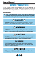
User’s Manual SAFETY PRECAUTIONS Do not attempt to install or operate your unit until you have read the safety precautions in this manual. Safety items throughout this manual are labeled with a Danger, Warning or Caution based on the risk type. DEFINITIONS ! This is the safety alert symbol. It is used to alert you to potential personal injury hazards. Obey all safety messages that follow this symbol to avoid possible injury or death.
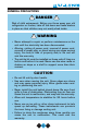
GENERAL PRECAUTIONS ! DANGER ! Risk of child entrapment. Before you throw away your old refrigerator or freezer, take off the doors and leave shelves in place so that children may not easily climb inside. ! WARNING • Never attempt to repair or perform maintenance on the unit until the electricity has been disconnected.
User’s Manual GENERAL PRECAUTIONS (CONTINUED) CAUTION • Using a heater to speed up defrosting can damage the inner lining. DO NOT use any type of electrical heater to defrost. • Use only genuine U-Line replacement parts. Imitation parts can reduce ice rate, cause water to overflow from ice maker mold, damage the unit, and may void the warranty.
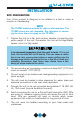
INSTALLATION SITE PREPARATION Your U-Line product is designed to be installed in a wall or under a counter or freestanding. NOTE The 75 BEV must be ordered for right or left hand door. The 75 BEV doors are not reversible. Any reference to reversing the door, does not apply to the 75 BEV. 1. Position the unit on a flat, level surface, capable of supporting the entire weight of the unit. Remember the unit will be significantly heavier once it is fully loaded.
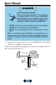
User’s Manual ! DANGER ! ELECTROCUTION HAZARD! Electrical Grounding Required. This appliance is equipped with a three prong (grounding) polarized plug for your protection against possible shock hazards. It must be plugged into a properly grounded three-prong receptacle. • NEVER remove the round grounding prong from the plug. • NEVER use a two-prong grounding adapter. • NEVER use an extension cord to connect power to the unit.
NOTE Keep in mind that the door of the unit may be mounted on either side of the cabinet (see REVERSING THE DOOR) except for the 75 BEV. All U-Line units have a zero clearance for the door to open when the hinge is on the right, except for Stainless Steel Doors. Additional clearance is needed for the Combo Models 29A, 29FF, and 75A only when the door hinge is on the left. See built-in installation for additional clearance requirements for these models.
User’s Manual LEVELING THE UNIT It is important that these units, primarily the ice maker assembly and 75 BEV are level. All 75 and 15 Series units are equipped with adjustable feet for leveling and height adjustment (Figure 3). All other units have rubber feet. To level units with adjustable feet: 1. Adjust all four leveling feet evenly so that the top of the cabinet is at the desired installation height and level. 2.
4. Place the unit in position where it is to be installed. Re-check cabinet height and levelness (Figure 4) and adjust if necessary.
User’s Manual CONNECTING THE WATER SUPPLY ICE MAKER MODELS ONLY Install a 1/4" outside diameter copper water line (not supplied with unit) from the nearest COLD water pipe. When connecting the water supply, follow these guidelines: • Review the local plumbing codes before you install the unit. • In most instances, the cold water supply will come from the basement through a hole in the floor. • The water pressure should be between 15 and 150 psi.
1. Locate the compression fitting and ferrule packed in the unit. Slide the compression fitting and ferrule over the 1/4" outside diameter water supply line. Do not use thread sealing compound or tape. Using two wrenches, tighten the compression fitting on the supply line (see Figure 6). Do not overtighten. UL134_CO Figure 6 2. Carefully bend the water supply line into position and connect the line to the solenoid valve (see Figure 7). Avoid kinking the water supply line.
User’s Manual WATER LINE UL104 Figure 9 NOTE On BI-95 and BI-98 models, route the water supply line through the unit so it does not come into contact with any internal components other than the solenoid valve (Figure 9). Normal operation creates some vibration. A water supply line contacting an internal component or cabinet wall can cause excessive noise during operation or damage to the line.
NOTE After completing the installation, turn on the water and recheck water connection for leaks. Apply additional tightening if needed. Do not use thread sealing compound or tape. 4. Plug in the power cord. 5. Gently push the unit into position. GRILLE INSTALLATION 1. With a standard blade screwdriver (or 1/4” nutdriver), remove the grille screw to attach the grille (Figure 11). GRILLE SCREW UL106 Figure 11 2. Remove the control knob by pulling it toward you. 3.
User’s Manual 4. Place the two hook-hinges (located on the rear bottom side of the grille) on the front lip of the unit base. Swing the grille up into position, aligning the grille and cabinet screw hole (Figure 12). UL107 Figure 12 5. Insert the screw. Do not to overtighten. 6. Reinstall control knob.
95 AND 98 MODELS 1. With a standard blade screwdriver (or 1/4" nutdriver), remove the screw needed to attach the grille (see Figure 13). 2. Carefully remove the grille from inside the unit. Locate the screw hole at the top, middle recessed section of the grille. 3. Place the two hook-hinges (located on the rear bottom side of the grille) on the front lip of the unit base. Swing the grille up into position, aligning the grille and cabinet screw holes (see Figure 14).
User’s Manual GLASS SHELF INSTALLATION (for models with Glass Shelves) 1. Carefully remove the glass shelves from the packaging. UL108a 75 BEV Figure 15 2. Slide the shelves onto lower two sets of ribs, making sure the silver edge strip is toward the front of the unit and the decorative graphics are on the underside of the shelves. Make sure the shelves are inserted fully into the unit (Figure 15). The white edge strip toward the rear prevents cans and bottles from freezing against the cold evaporator.
BUILT-IN INSTALLATION Your U-Line product is designed to be built-in or freestanding. When built-in, they do not require additional air space for the top, sides, or rear. However, the front grille must NOT be obstructed. NOTE Required for ease of installation and door opening, you must allow an additional 1/4" to width of unit. Unit Dimensions NOTE 29A, 29FF Combo Models, and 75A require additional clearance when the door opens from the right (Figures 16 and 17).
User’s Manual CUSTOM DOOR PANEL INSERT NOTE The SP18 and 75 BEV models are not designed to accept custom door panels. A custom door panel can be installed on your U-Line unit to harmonize with or accent the surrounding decor. The door will accept a flat or raised panel. The maximum panel thickness where inserted into the door reveal (channel) is 1/4” thick. For raised panels, the depth of the reveal is 1/4” on the sides and bottom, and 1/2” on the top.
Install the insert as follows: ! Insert edges may be SHARP! Use care when installing. 1. Remove top hinge screw pin (large Phillips head, Figure 18). Hold door to keep it from falling. 2. Remove door, being careful not to scratch top of door on hinge. 3. Pull door gasket out of groove (top edge of door only). Start in the middle and pull outward, moving toward the edge (Figure 19). This may take some force. Figure 19 UL131 Figure 18 4. Remove two small screws holding door handle.
User’s Manual NOTE Use care not to bend light switch bracket (where installed), located on door bottom when installing door insert. Do not set door on bottom edge when pushing insert into place. 6. Slide custom door panel insert into 1/4" channel in door front. 7. Holding door gasket out of the way, replace handle on door making sure it is seated properly on insert and that screw holes line up. 8. Install two small screws removed in step 4. 9.
To add a final finish coat: 1. Remove the top two racks. See WINE RACK REMOVAL/ INSTALLATION. 2. Remove screws securing wood trim to the two racks attached at the drawer slides so wood can be removed for treatment. 3. Lightly scruff sand the wood trim with 280 grit 3M™ Tri-M-Ite™ sandpaper. 4. Remove sanding dust with a clean, dry cloth. 5. Apply a thin coat of a clear protective finish; the factory-applied seal is compatible with virtually all finishes.
User’s Manual To stain for a different wood color: 1. Remove the top two racks. See WINE RACK REMOVAL/ INSTALLATION. 2. Remove screws securing wood trim to the two racks attached at the drawer slides so wood can be removed for treatment. 3. Apply Minwax® Water-Based Wood Stain to wood with a synthetic bristle brush or a foam applicator. Stain must penetrate approximately three minutes. After this period, while stain is still wet, take a stain dampened rag and remove all excess stain.
WINE RACK REMOVAL/INSTALLATION To remove the wine racks for cleaning or refinishing: UL302 Figure 21 1. Grasp the end of the wine rack, sliding it out and up. 2. Clean wine rack with a clean dampened cloth. To insert the wine racks: 1. Position the wine rack above the shelf channel where the rack is to be inserted (Figure 21). 2. Slide the rack on the channel at an angle until the rack is in the channel. 3. Continue sliding until the rack is all the way into the cabinet.
User’s Manual REVERSING THE DOOR Depending upon the location of the unit, it may be desirable to change the side on which the door is mounted. NOTE On Combo Models 29A and 29FF (built-in installations only), changing the door mounting to the left side may interfere with ice bucket removal. See BUILT-IN INSTALLATION section for clearance requirements. To reverse the door mounting on Models SP18, BI-95, BI-98, 15R, 29R, Combo 29A, and Combo 29FF (except Stainless Steel models), perform the following: 1.
UL111 UL112 Figure 24 Figure 26 BUSHING UL113 UL110 Figure 25 Figure 27 6. Relocate plastic spacer/bushing on bottom of door to opposite side, and place door on bottom hinge pin (Figure 27). Clean out bushing hole in door bottom with a screwdriver if needed. 7. Remove plastic hole plug from door handle and relocate on opposite side (Figure 28).
User’s Manual 8. Remove pivot screw from top hinge, invert screw and reinstall pivot screw in top hinge (Figure 28). HINGE RIGHT SIDE DOOR SWING LEFT SIDE DOOR SWING PLASTIC PLUG HOLE PLASTIC PLUG HOLE RIGHT SIDE HINGE SCREW INVERT SCREW INVERT HINGE UL115 Figure 28 9. Remove three plastic screw 11. Fasten upper hinge to unit plugs in hinge holes, top of (three screws). Partially tightcabinet, opposite side. Be en screws until door is aligned careful not to scratch cabinet (Figure 30). (Figure 29).
12. Adjust door to assure proper seal. Tighten upper hinge screws securely. 13. Replace three plastic plugs removed in step 8 into holes on top of unit. Replace screws in holes in bottom of unit, opposite side. 14. Reinspect door seal and alignment. Adjust if needed. 15. Reinstall grille (one screw). NOTE On Combo Model 75A (built-in installations only), changing the door mounting to the left side may interfere with ice bucket removal. See BUILT-IN INSTALLATION section for clearance requirements.
User’s Manual 8. Install bottom hinge on cabicabinet, opposite side, aligning flat edge of hinge with outer edge of unit. Partially tighten screws (Figure 32). 9. Relocate plastic spacer/ bushing on bottom of door to opposite side (Figure 27). Clean out bushing hole in door bottom with a screwdriver if needed. UL129 Figure 32 10. Place door on lower hinge pin. Align flat edge of top hinge with outer edge of unit and fasten upper hinge to unit (four screws).
REVERSING A STAINLESS STEEL DOOR Stainless Steel models are field reversible for left or right hand opening. The door opening is easily reversed by moving the hinge hardware to the opposite side (Figure 33) as follows: 1. Remove the bottom (two screws) from door. hinge 2. Remove top hinge (two screws) from door. 3. Remove door. 4. Remove top hinge (four screws) from cabinet. Invert and install on bottom, opposite side of cabinet. 5. Remove bottom hinge (four screws) from cabinet.
User’s Manual ALIGNING THE DOOR For proper door alignment: UL109 Figure 34 1. Loosen top and bottom hinge screws (Figure 34). 2. Align door squarely with cabinet. 3. Make sure the gasket is firmly in contact with cabinet all the way around the door (no gaps). 4. Tighten bottom hinge screws. 5. Tighten top hinge screws.
UL130 Figure 35 NOTE When inspecting door alignment, make sure the light switch bracket makes contact with the light switch plunger (Figure 35). Also, make sure the door gasket is not pinched on the hinge side of the door. WINE RACKS – 75 BEV The two wine racks in the 75 BEV are designed for storage as well as for display purposes. The racks hold up to eight bottles (750 ML size) each. When the Beverage Center door is opened, the wine racks can be slid outward by pulling on the front of the racks.
User’s Manual INITIAL START-UP AND ADJUSTING THE TEMPERATURE CONTROL U-Line recommends the unit be allowed to run overnight and make ice on ice-maker models prior to loading with product. It is possible that dirt or scale will dislodge in the water line. Always throw away all ice cubes made during the first two to three hours of operation. Once the installation is complete, the unit is ready for initial start-up and operation. NOTE BI-95 and BI-98 models have the ON-OFF switch behind the front grille.
Allow unit temperature to stabilize for 24 hours before use. 4. Open the water supply valve in the main water source. As soon as the ice maker mold reaches the proper temperature, the ice maker mechanism will fill the mold with water. The first cubes may be small because of air in the water line. Subsequent cubes will be of standard size. Approximate time for the first cycle is 45 minutes. Allow two hours for Frostfree models.
User’s Manual Factors which affect the internal temperatures of the cabinet include: 1. Temperature setting. 2. Room temperature where used or installed. 3. Number of times the door is opened and closed. 4. Amount of time the internal light is illuminated. This affects primarily wines on the top racks. 5. Use or installation in direct sun light or near a heat source.
NORMAL OPERATION On units with refrigerator sections, the unit has been designed to achieve a fresh food temperature of approximately 38°F. Units with with a freezer section (ice maker) are designed to have a freezer temperature of approximately 15°F. On units with ice makers, when the ice bucket is full, the ice making mechanism will shut off. However, the refrigeration system will continue to cool and maintain the cube supply.
User’s Manual If ice maker is not used regularly, the ice bucket should be emptied periodically to ensure fresh cubes. It is normal for cubes to appear cloudy. This is caused by air being trapped in the water due to fast freezing. It has nothing to do with the health, taste or chemical make-up of the water. It is the same air that is in every glass of water you drink. To provide for higher ice rate (production of more cubes), adjust the temperature control to a warmer setting.
MARINE USE Many U-Line models are designed to operate in a harsh marine environment. Special considerations include the following: • For best performance, keep the unit out of direct sunlight. • On Ice Maker models, turn the unit OFF and dispose of any ice cubes if the unit will not be used for five days or more. Prop door open to allow for air circulation and prevent mold and mildew. Do not use antifreeze in your icemaker.
User’s Manual ADJUSTING ICE CUBE SIZE On models equipped with an ice maker, the cube size may be adjusted by changing the amount of water injected into the ice maker assembly. 1. Remove the ice maker assembly cover (Figure 39). 2. Locate the adjusting screw on the ice maker assembly control box. The adjusting screw is just below the minus (–) and plus (+) signs on the control box (see Figure 40). – + automatic ICE MAKER UL122 UL133 Figure 39 Figure 40 3.
CAUTION Use only genuine U-Line replacement parts. U-Line ice maker parts are not the same as standard FSP Whirlpool parts. Using non U-Line parts can reduce ice rate, cause water to overflow from ice maker mold, damage the unit, and may void the warranty. Using non U-Line parts can reduce ice rate, cause water to overflow from ice maker mold, damage the unit, and may void the warranty. LIGHT SWITCH AND BULB All 75 Series units have interior lights, which are illuminated when the door is opened.
User’s Manual LIGHT BULB REPLACEMENT 1 TAB 2 3 UL305_BEV Figure 41 Light bulb replacement is simple. 1. Remove the light housing cover by sliding the cover toward the tab, swinging the end opposite the tab down and pulling down and away (Figure 41). 2. Replace bulb with genuine ULine replacement. ! WARNING Do not use any other replacement bulb than the one recommended. 3. Replace the light housing cover by inserting the tab FIRST, sliding the cover toward the tab and pushing up the other end.
PROPER STORAGE and STOCKING RECOMMENDATIONS Your Beverage Center will accommodate up to 16 bottles (750 ML size) on the wine racks: up to eight bottles on each rack. Specially designed wine racks allow for the proper horizontal storage and presentation of the wine. The cork remains moist, which keeps air from entering the bottle. UL138 Figure 42 The 75 BEV should be stocked beginning at the back of the bottom rack and working forward. Stagger the bottles as shown in Figure 42.
User’s Manual CLEANING & MAINTENANCE Periodic cleaning and proper maintenance will ensure efficiency, top performance, and long life. The maintenance intervals listed are based on normal conditions. You may want to shorten the intervals if you have pets, the unit is used outdoors, or other special considerations. Exterior Cleaning – As Required The door, grille and cabinet may be cleaned with a mild detergent and warm water solution. Do not use solvent based or abrasive cleaners.
Condenser Cleaning – Every Three Months ! WARNING Disconnect electric power to the unit before cleaning the condenser or the solenoid valve. UL005A Figure 43 Keep the front grille free of dust and lint to allow air to flow to the condenser (Figure 43). Clean the condenser coil, located behind the front grille. Use a brush or vacuum cleaner to remove dirt, lint and other accumulations from the condenser coil.
User’s Manual ! WARNING DO NOT touch the condenser fins. The condenser fins are SHARP and can be easily damaged. 4. Clean the condenser coil using a soft brush with a “combing” action or vacuum cleaner. Do not touch the condenser coil. The condenser coil may be located on either the right or left side of the base. UL107 Figure 45 5. Place the two hook-hinges (located on the rear bottom side of the grille) on the front lip of the unit base.
UL123 Figure 46 3. Use a tooth brush to clean sediment from the inlet screen (Figure 46). DO NOT remove the screen. 4. Attach the hose connector to the solenoid valve. Tighten connector securely with pliers. Open the water supply valve and check for leaks at the hose connector. DEFROSTING CAUTION DO NOT use any type of electrical heating device, ice pick, knife, or other sharp instrument to defrost, as this could damage the inner lining or refrigeration system and void the warranty.
User’s Manual STORAGE If the unit is to be stored or not used for extended periods: 1. Remove all contents from the unit. 2. Shut off water supply at the main water source. 3. Disconnect the water supply line from the solenoid valve. 4. Disconnect the water line from the solenoid valve outlet and drain the system of water. 5. Allow the unit to run for one hour or more until all remaining ice cubes have been ejected from the ice maker assembly. 6. Remove all ice from the ice bucket. 7.
TROUBLESHOOTING BEFORE CALLING FOR SERVICE If the unit appears to be malfunctioning, read through NORMAL OPERATION first. If the problem persists, check the TROUBLESHOOTING GUIDE. Locate the problem in the guide and refer to the cause and its remedy before calling for service. The problem could be something very simple which can be solved without a service call.
User’s Manual Problem The unit is not cold enough (cont.) Possible Cause Airflow to front grille blocked Temperature not set cold enough The unit is not cold enough (Frost free units only) The unit frosts up Water is leaking out the back of the unit Ice cubes sticking together Noise during operation The door was left open causing the evaporator behind the back wall to fill with frost preventing proper air flow and cooling.
Problem No ice Possible Cause Bin arm locked in upright position No water to unit. Remedy Lower bin arm. Water leaks into ice bucket Water level set too high Fresh food section on Combo units too cold Ice bucket not fully inserted Turn on water or contact plumber. Adjust control to a warmer setting (COUNTERCLOCKWISE). Set cube size smaller. See ADJUSTING ICE CUBE SIZE. Clean condenser. See CLEANING AND MAINTENANCE. Set cube size smaller. See ADJUSTING ICE CUBE SIZE. Push ice bucket into place.
User’s Manual SPECIFICATIONS Unit Type Ice Makers Model Number Ice Production Capacity (per day) Cube Storage Capacity SP18 18 lbs. (8 kg) 12 lbs. (5 kg) Manual BI-95 23 lbs. (10 kg) 12 lbs. (5 kg) Manual BI-98 25 lbs. (11 kg) 25 lbs. (11 kg) Manual 75A 22.5 lbs. (10 kg) 13 lbs. (6 kg) 4.2 cu. ft. (119 L) Manual 29FF 8 lbs. (4 kg) 13 lbs. (6 kg) 2.1 cu. ft. (60 L) Frost Free 29A 22 lbs. (10 kg) 13 lbs. (6 kg) 2.1 cu. ft. (60 L) Manual 75R 6 cu. ft.
Bev Center Cover 8/4/04 1:37 PM Page 2 U-LINE CORPORATION LIMITED WARRANTY U-Line Corporation warrants each U-Line product to be free from defects in materials and workmanship for a period of one year from the date of purchase; and warrants the sealed system (consisting of the compressor, the condenser, the evaporator, the hot gas bypass valve, the dryer and the connecting tubing) in each U-Line product to be free from defects in materials and workmanship for a period of five years from the date of purc
8/4/04 1:37 PM Page 1 P.O. Box 245040 Milwaukee, WI 53224-9540 Phone 414.354.0300 FAX 414.354.7905 www.U-Line.com Printed in U.S.A.