9/2/03 3:45 PM Page 1 P.O. Box 245040 Milwaukee, WI 53224-9540 Phone 414.354.0300 FAX 414.354.7905 www.U-Line.com Printed in U.S.A. P/N 41923 (Rev.
Inside Front Cover 41923 9/2/03 3:45 PM Page 1 U-LINE CORPORATION LIMITED WARRANTY U-Line Corporation warrants each U-Line product to be free from defects in materials and workmanship for a period of one year from the date of purchase; and warrants the sealed system (consisting of the compressor, the condenser, the evaporator, the hot gas bypass valve, the dryer and the connecting tubing) in each U-Line product to be free from defects in materials and workmanship for a period of five years from the date
Users Manual 41923 9/2/03 3:44 PM Page 1 INTRODUCTION Congratulations on your purchase of U-Line ice making or refrigeration products. A pioneer in the field for more than 30 years, U-Line is the world’s number one manufacturer of built-in, under-counter ice making and specialty refrigeration products. U-Line dedicates 100% of its research and development to these products. The result: U-Line technology leads the market with new ideas and superior craftsmanship.
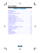
Users Manual 41923 9/2/03 3:44 PM Page 2 User’s Manual TABLE OF CONTENTS INTRODUCTION..........................................................................1 SAFETY PRECAUTIONS ...............................................................3 INSTALLATION ...........................................................................5 CONNECTING THE WATER SUPPLY ..............................................7 LEVELING THE UNIT ...................................................................
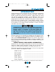
Users Manual 41923 9/2/03 3:44 PM Page 3 SAFETY PRECAUTIONS Do not attempt to install or operate your unit until you have read the safety precautions in this manual. Safety items throughout this manual are labeled with a Danger, Warning or Caution based on the risk type. DEFINITIONS ! This is the safety alert symbol. It is used to alert you to potential personal injury hazards. Obey all safety messages that follow this symbol to avoid possible injury or death.
Users Manual 41923 9/2/03 3:44 PM Page 4 User’s Manual GENERAL PRECAUTIONS ! DANGER ! Risk of child entrapment. Before you throw away your old refrigerator or freezer: Take off the doors, leave shelves in place so that children may not easily climb inside. ! • Never attempt to repair or perform maintenance on the unit until the electricity has been disconnected.
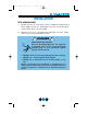
Users Manual 41923 9/2/03 3:44 PM Page 5 INSTALLATION SITE PREPARATION 1. Position the unit on a flat, level surface, capable of supporting the entire weight of the unit. Remember that the unit will be significantly heavier once it is fully loaded. 2. Connect the unit to a grounded and polarized 115 VAC, 60Hz, 15A circuit (normal household current). ! DANGER ! ELECTROCUTION HAZARD! Electrical Grounding Required.
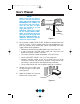
Users Manual 41923 9/2/03 3:44 PM Page 6 User’s Manual NOTE Keep in mind that the door of the unit may be mounted on either side of the cabinet (see REVERSING THE DOOR). All U-Line units have a zero clearance for the door to open when the handle is on the right (see Figure 1). Additional clearance is needed for Combo Models 29A, 29FF, and 75A only, when the door handle is on the left. See BUILT-IN INSTALLATION for additional clearance requirements for these models.
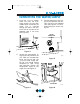
Users Manual 41923 9/2/03 3:44 PM Page 7 CONNECTING THE WATER SUPPLY 1. Install the 1/4 inch copper water line from the main water source. On ice maker models BI-95 and BI-98, the water line is inserted through the hole in the rear of the unit to connect to the solenoid valve in the front (see Figure 3). 3. Carefully bend the water supply line into position and connect the line to the solenoid valve (see Figures 5 and 6). Avoid kinking the water supply line.
Users Manual 41923 9/2/03 3:44 PM Page 8 User’s Manual 4. For recessed installations, allow extra water supply line length to provide slack for easy removal from the recessed area (see Figure 7). This will also safeguard against kinking the line. NOTE If you are not intending to use the ice maker and do not connect the water supply (or turn the supply valve off), it is imperative to raise the bin arm of the ice maker (see Figure 8).
Users Manual 41923 8. 9/2/03 3:44 PM Page 9 Allow at least 1-1/2 inches clearance behind the unit for electrical and water supply connections. LEVELING THE UNIT It is important that the unit, primarily the ice maker assembly, is level. All 75 and 15 Series units are equipped with adjustable feet for leveling and height adjustment (see Figure 9). All other units have rubber feet. TURN FOOT TO ADJUST UL105 Figure 9 GRILLE INSTALLATION NOTE Model SP18 Icemakers come with the grille already installed.
Users Manual 41923 9/2/03 3:44 PM Page 10 User’s Manual GRILLE SCREW UL106 Figure 10 4. Place the two hook-hinges (located on the rear bottom side of the grille) on the front lip of the unit base. Swing the grille up into position, aligning the grille and cabinet screw holes (see Figure 11). UL107 Figure 11 5. Insert the screw, being careful not to over tighten. 6. Reinstall control knob.
Users Manual 41923 9/2/03 3:44 PM Page 11 95 AND 98 MODELS 1. With a standard blade screwdriver (or 1/4" nutdriver), remove the screw needed to attach the grille (see Figure 12). 2. Carefully remove the grille from inside the unit. Locate the screw hole at the top, middle recessed section of the grille. 3. Place the two hook-hinges (located on the rear bottom side of the grille) on the front lip of the unit base.
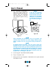
Users Manual 41923 9/2/03 3:44 PM Page 12 User’s Manual GLASS SHELF INSTALLATION (FOR MODELS WITH GLASS SHELVES) 1. Carefully remove the shelves from inside the unit and remove the packaging. 2. Slide the shelves onto desired ribs, making sure that the silver edge strip is toward the front of the unit and the decorative graphics are on the underside of the shelves. Make sure the shelves are inserted fully into the unit (see Figure 14).
Users Manual 41923 9/2/03 3:44 PM Page 13 REVERSING THE DOOR Depending upon the location of the unit, it may be desirable to change the side on which the door is mounted. NOTE On Combo Models 29A and 29FF (built-in installations only), changing the door mounting to the left side may interfere with ice bucket removal. See BUILT-IN INSTALLATION section for clearance requirements.
Users Manual 41923 9/2/03 3:44 PM Page 14 User’s Manual UL111 UL112 Figure 19 Figure 17 BUSHING UL113 UL110 Figure 20 Figure 18 6. Relocate plastic spacer/bushing on bottom of door to opposite side, and place door on bottom hinge pin (see Figure 20). Clean out bushing hole in door bottom with a screwdriver if needed. 7. Remove plastic hole plug from door handle and relocate on opposite side. See Figure 21.
Users Manual 41923 8. 9/2/03 3:44 PM Page 15 Remove pivot screw from top hinge, invert screw and reinstall pivot screw in top hinge. See Figure 19. HINGE RIGHT SIDE DOOR SWING LEFT SIDE DOOR SWING PLASTIC PLUG HOLE PLASTIC PLUG HOLE RIGHT SIDE HINGE SCREW INVERT SCREW INVERT HINGE UL115 Figure 21 9. Remove three plastic screw 11. Fasten upper hinge to unit (3 plugs in hinge holes, top of screws). Partially tighten cabinet, opposite side. Be screws until door is aligned.
Users Manual 41923 9/2/03 3:44 PM Page 16 User’s Manual 12. Adjust door to assure proper seal. Tighten upper hinge screws securely. 13. Replace three plastic plugs removed in step 8 into holes on top of unit. Replace screws in holes in bottom of unit, opposite side. 14. Reinspect door seal and alignment. Adjust if needed. 15. Reinstall grille (1 screw). NOTE On Combo Model 75A (built-in installations only), changing the door mounting to the left side may interfere with ice bucket removal.
Users Manual 41923 9/2/03 3:44 PM Page 17 8. Install bottom hinge on cabinet, opposite side, aligning flat edge of hinge with outer edge of unit. Partially tighten screws. See Figure 25. 9. Relocate plastic spacer/ bushing on bottom of door to opposite side, and place door on bottom hinge pin (see Figure 20). Clean out bushing hole in door bottom with a screwdriver if needed. UL129 Figure 25 10. Place door on lower hinge pin.
Users Manual 41923 9/2/03 3:44 PM Page 18 User’s Manual REVERSING A STAINLESS STEEL DOOR Stainless Steel models are field reversible for left or right hand opening. The door opening is easily reversed by moving the hinge hardware to the opposite side (see Figure 26) as follows: 1. Remove the bottom hinge (2 screws) from door. 2. Remove top hinge (2 screws) from door. 3. Remove door. 4. Remove top hinge (4 screws) from cabinet. Invert and install on bottom, opposite side of cabinet. 5.
Users Manual 41923 9/2/03 3:44 PM Page 19 NOTE When inspecting door alignment, make sure that the light switch bracket (where equipped) makes contact with the light switch plunger (see Figure 27). Also, make sure that the door gasket is not pinched too tightly on the hinge side of the door. UL130 Figure 27 CUSTOM DOOR PANEL INSERT INSTALLATION A custom door panel insert can be installed in most U-Line units. The door will accept a flat or raised panel.
Users Manual 41923 9/2/03 3:44 PM Page 20 User’s Manual Install the insert as follows: ! Insert edges may be SHARP! Use care when installing. 1. Remove top hinge screw pin (large Phillips head, see Figure 28). Hold door to keep it from falling. 2. Remove door, being careful not to scratch top of door on hinge. 3. Pull door gasket out of groove (top edge of door only). Start in the middle and pull outward, moving toward the edge (see Figure 29). This may take some force. UL131 Figure 28 4.
Users Manual 41923 9/2/03 3:44 PM Page 21 NOTE Use care not to bend light switch bracket (where installed), located on door bottom when installing door insert. Do not set door on bottom edge when pushing insert into place. 6. Slide custom door panel insert into 1/4 inch channel in door front. 7. Holding door gasket out of the way, replace handle on door making sure it is seated properly on insert and that screw holes line up. 8. Install two small screws removed in step 4.
Users Manual 41923 9/2/03 3:44 PM Page 22 User’s Manual NOTE To ease unit installation and removal, increase the Unit Dimension measurements. It is recommended that the cabinet rough opening dimensions be increased by at least 1/4" over the dimensions given for your unit. W D H UL118 Figure 31 AT LEAST 9" REQUIRED IF UNIT IS INSTALLED ADJACENT TO CABINET OR WALL. 9.000 AT LEAST 1" CLEARANCE REQUIRED IF UNIT IS INSTALLED FLUSH WITH CABINET OR WALL. 1.
Users Manual 41923 9/2/03 3:44 PM Page 23 INITIAL START-UP Once installation is complete, the unit is ready for initial start-up and operation. NOTE Models BI-95 and BI-98 have the ON-OFF switch behind the front grille. A small opening in the top of the grille is provided to access the switch (see Figure 34). Some models may also turn off when the temperature control is turned all the way towards warmer until it stops (clicks). UL503 Figure 34 1.
Users Manual 41923 9/2/03 3:44 PM Page 24 User’s Manual NORMAL OPERATION On units with refrigerator sections, the unit has been designed to achieve a fresh food temperature of approximately 38°F (temperature may vary due to ambient temperature). On units with ice makers, when the ice bucket is full, the ice making mechanism will shut off. However, the refrigeration system will continue to cool and maintain the cube supply.
Users Manual 41923 9/2/03 3:44 PM Page 25 It is normal for cubes to appear cloudy. This is caused by air being trapped in the water due to fast freezing. It has nothing to do with the health, taste or chemical make-up of the water. It is the same air that is in every glass of water you drink. To provide for higher ice rate (production of more cubes), adjust the temperature control to a warmer setting. If hollow cubes result, adjust temperature somewhat colder.
Users Manual 41923 9/2/03 3:44 PM Page 26 User’s Manual MARINE USE Many U-Line models are designed to operate in a harsh marine environment. Special considerations include the following: • For best performance, keep the unit out of direct sunlight. • On Ice Maker models, turn the unit OFF and dispose of any ice cubes if the unit will not be used for 5 days or more. Prop door open to allow for air circulation and prevent mold and mildew. Do not use antifreeze in your icemaker.
Users Manual 41923 9/2/03 3:44 PM Page 27 ADJUSTING ICE CUBE SIZE On models equipped with an ice maker, the cube size may be adjusted by changing the amount of water injected into the ice maker assembly. 1. Remove the ice maker assembly cover (see Figure 39). 2. Locate the adjusting screw on the ice maker assembly control box. The adjusting screw is just below the minus (–) and plus (+) signs on the control box (see Figure 40). – + UL122 UL133 Figure 39 Figure 40 3.
Users Manual 41923 9/2/03 3:44 PM Page 28 User’s Manual CARE AND CLEANING Periodic cleaning and proper maintenance will ensure efficiency, top performance, and long life. We suggest the following: • The interior may be cleaned with a mild detergent and warm water. • Avoid the use of solvent cleaning agents or abrasives on the interior. These cleansers may transmit taste to the ice cubes and food, or damage or discolor the interior. • The exterior may be cleaned with a mild detergent and warm water.
Users Manual 41923 9/2/03 3:44 PM Page 29 LIGHT BULB REPLACEMENT Light bulb replacement is simple. 1. 2. 3. 1 Remove the light housing cover by sliding the cover toward the tab, swinging the end opposite the tab down and pulling down and away (see Figure 43). Replace bulb with genuine U-Line replacement. Replace the light housing cover by inserting the tab FIRST, sliding the cover toward the tab and pushing up the other end. You should hear a snap/click.
Users Manual 41923 9/2/03 3:44 PM Page 30 User’s Manual DEFROSTING CAUTION DO NOT use any type of electrical heating device, ice pick, knife, or other sharp instrument to defrost, as this could damage the inner lining or refrigeration system and void the warranty. Manual defrost models should be defrosted approximately every 8 weeks. However, this interval may not be adequate in periods of high humidity or heavy usage. Defrost your unit whenever the frost thickness is 1/4” or greater.
Users Manual 41923 9/2/03 3:44 PM Page 31 TROUBLESHOOTING BEFORE CALLING FOR SERVICE If the unit appears to be malfunctioning, read through NORMAL OPERATION first. If the problem persists, check the TROUBLESHOOTING GUIDE. Locate the problem in the guide and refer to the cause and its remedy before calling for service. The problem could be something very simple which can be solved without a service call.
Users Manual 41923 9/2/03 3:44 PM Page 32 User’s Manual Problem The unit frosts up Water is leaking out the back of the unit Ice cubes sticking together Possible Cause Unit is manual defrost model Door gasket not sealing properly High ambient temperatures or humidity Water supply connection leaking Noise during operation Door gasket not sealing properly Infrequent use of cubes Copper water supply tubing contacting internal components Certain sounds are normal.
Users Manual 41923 9/2/03 3:44 PM Page 33 IF SERVICE IS REQUIRED If the need for service arises, contact the dealer from whom the unit was purchased. State the Model Number and Serial Number and explain the problem. The Model and Serial Number plate is located inside unit at upper right hand corner. If you do not know the name of the selling dealer or local service company, you can check online at www.U-LineService.com.
Users Manual 41923 9/2/03 3:44 PM Page 34 User’s Manual 34
9/2/03 3:45 PM Page 1 P.O. Box 245040 Milwaukee, WI 53224-9540 Phone 414.354.0300 FAX 414.354.7905 www.U-Line.com Printed in U.S.A. P/N 41923 (Rev.