USER GUIDE SAFETY • INSTALLATION & INTEGRATION • OPERATING INSTRUCTIONS • MAINTENANCE • SERVICE RIGHT PRODUCT. RIGHT PLACE. RIGHT TEMPERATURE. SINCE 1962.
USER GUIDE u-line.
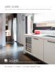
USER GUIDE u-line.com WELCOME TO U-LINE Congratulations on your U-Line purchase. Your product comes from a company with over five decades and three generations of premium modular ice making, refrigeration, and wine preservation experience. U-Line continues to be the American leader, delivering versatility and flexibility for multiple applications including residential, light commercial, outdoor and marine use.
USER GUIDE u-line.com SAFETY • INSTALLATION & INTEGRATION • OPERATING INSTRUCTIONS • MAINTENANCE • SERVICE Safety and Warning ! DANGER NOTICE This unit contains R600a (Isobutane) which is a Please read all instructions before installing, flammable hydrocarbon. It is safe for regular operating, or servicing the appliance. use. Do not use sharp objects to expedite defrosting.
USER GUIDE u-line.com SAFETY • INSTALLATION & INTEGRATION • OPERATING INSTRUCTIONS • MAINTENANCE • SERVICE Disposal and Recycling ! DANGER RISK OF CHILD ENTRAPMENT. Before you throw away your old refrigerator or freezer, take off the doors and leave shelves in place so children may not easily climb inside.
USER GUIDE u-line.com SAFETY • INSTALLATION & INTEGRATION • OPERATING INSTRUCTIONS • MAINTENANCE • SERVICE Environmental Requirements This model is intended for indoor/interior applications only and is not to be used in installations that are open/ exposed to natural elements. This unit is designed to operate between 50°F (10°C) and 100°F (38°C). Higher ambient temperatures may reduce the unit’s ability to reach low temperatures and/or reduce ice production on applicable models.
USER GUIDE u-line.com SAFETY • INSTALLATION & INTEGRATION • OPERATING INSTRUCTIONS • MAINTENANCE • SERVICE Electrical ! WARNING SHOCK HAZARD — Electrical Grounding Required. Never attempt to repair or perform maintenance on the unit until the electricity has been disconnected. Never remove the round grounding prong from the plug and never use a two-prong grounding adapter.
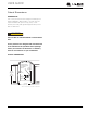
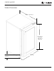
USER GUIDE u-line.com SAFETY • INSTALLATION & INTEGRATION • OPERATING INSTRUCTIONS • MAINTENANCE • SERVICE Cutout Dimensions PREPARE SITE Your U-Line product has been designed exclusively for a built-in installation. When built-in, your unit does not require additional air space for top, sides, or rear. However, the front grille (plinth strip/base fascia) must NOT be obstructed. ! CAUTION Unit can NOT be installed behind a closed cabinet door.
USER GUIDE u-line.
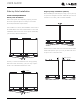
USER GUIDE u-line.com SAFETY • INSTALLATION & INTEGRATION • OPERATING INSTRUCTIONS • MAINTENANCE • SERVICE Side-by-Side Installation OTHER SITE REQUIREMENTS Side-by-Side Installation Hinge-by-Hinge Installation (Mullion) When installing two units hinge-by-hinge, 13/16" (22 mm) is required for integrated models. Additional space may be needed for any knobs, pulls or handles installed.
USER GUIDE u-line.com SAFETY • INSTALLATION & INTEGRATION • OPERATING INSTRUCTIONS • MAINTENANCE • SERVICE Anti-Tip Bracket SIDE MOUNT Left Hinged Cabinet Right Hinged Cabinet ! CAUTION The anti-tip bracket must be installed to prevent the unit from tipping when doors are fully opened or excess weight is placed on the front of the unit. The anti-tip bracket has multiple mounting options. Mounting will depend on your particular cabinet configuration. Locate 3 #8x5/8" screws included with your unit.
USER GUIDE u-line.com SAFETY • INSTALLATION & INTEGRATION • OPERATING INSTRUCTIONS • MAINTENANCE • SERVICE General Installation INSTALLATION 1. Plug in the power/electrical cord. LEVELING INFORMATION 1. Use a level to confirm 2. Gently push the unit into position. Be careful not to the unit is level. Level entangle the cord. should be placed along top edge and side 1 3. Re-check the leveling, from front to back and side to edge as shown. side. Make any necessary adjustments.
USER GUIDE u-line.com SAFETY • INSTALLATION & INTEGRATION • OPERATING INSTRUCTIONS • MAINTENANCE • SERVICE 1. Use the dimensions provided in the diagram to cut and shape your integrated grille (plinth strip/base fascia) 3-5/16" (84 mm) 1" (25 mm) PREPARE AND INSTALL INTEGRATED GRILLE (PLINTH STRIP/BASE FASCIA) INTEGRATED GRILLE (PLINTH STRIP/BASE FASCIA) DIMENSIONS 1-9/16" (40 mm) Integrated Grille - Plinth Dimensions panel. Recommended panel thickness is between 1/4" (6 mm) and 3/8" (9 mm).
USER GUIDE u-line.com SAFETY • INSTALLATION & INTEGRATION • OPERATING INSTRUCTIONS • MAINTENANCE • SERVICE Grille - Plinth Installation REMOVING AND INSTALLING GRILLE (PLINTH STRIP/BASE FASCIA) ! WARNING Disconnect electric power to the unit before removing the grille (plinth strip/base fascia). When using the unit, the grille (plinth strip/base fascia) must be installed. ! WARNING DO NOT touch the condenser fins. The condenser fins are SHARP and can be easily damaged.
USER GUIDE u-line.com SAFETY • INSTALLATION & INTEGRATION • OPERATING INSTRUCTIONS • MAINTENANCE • SERVICE Door Swing For Integrated models that are installed adjacent to a wall, Wall 1/4" (6 mm) 1/4" (6 mm) clearance is recommended from wall on hinge side to allow the door to open 90°. Allow for additional space for any knobs or pulls installed on the integrated panel/frame.
USER GUIDE u-line.com SAFETY • INSTALLATION & INTEGRATION • OPERATING INSTRUCTIONS • MAINTENANCE • SERVICE Door Stop 3. Once cover is removed, slide hinge pin into hole as shown. Pin should slide into place, stopping the door at Your U-Line unit was shipped to you with the optional 90° 90°; if the pin does not go into the hole shown, hold pin. the door less than 90° open and try again. Your unit’s door(s) will open 115° straight from the factory.
USER GUIDE u-line.com SAFETY • INSTALLATION & INTEGRATION • OPERATING INSTRUCTIONS • MAINTENANCE • SERVICE Door Adjustments DOOR ALIGNMENT AND ADJUSTMENT Align and adjust the door if it is not level or is not sealing properly. If the door is not sealed, the unit may not cool T-25 Torx Screw properly, or excessive frost or condensation may form in the interior. NOTICE Properly aligned, the door’s gasket should be firmly in contact with the cabinet all the way T-25 Torx Screw around the door (no gaps).
USER GUIDE u-line.com SAFETY • INSTALLATION & INTEGRATION • OPERATING INSTRUCTIONS • MAINTENANCE • SERVICE 3. Using T-25 Torx bit loosen screw #1 and remove screw #2 on top and bottom hinge. Slide and remove the door from unit. Completely remove screw #1 on top and bottom. 2 1 4. Remove caps from screw heads on opposite side (2 on top and 2 on bottom). Using #2 Phillips bit remove the 4 underlying screws. Reinstall the screws and caps on the opposite side. 5.
USER GUIDE u-line.com SAFETY • INSTALLATION & INTEGRATION • OPERATING INSTRUCTIONS • MAINTENANCE • SERVICE Wood Trim Finishing The wine rack fronts are solid natural beech wood. They are factory coated with a clear vinyl sealer, which will sufficiently protect the wood in normal use. You may coat the trim with stain and/or a final finish to match surrounding cabinetry.
USER GUIDE u-line.com SAFETY • INSTALLATION & INTEGRATION • OPERATING INSTRUCTIONS • MAINTENANCE • SERVICE First Use All U-Line controls are preset at the factory. Initial startup requires no adjustments. NOTICE U-Line recommends allowing the unit to run overnight before loading with product. When plugged in, the unit will begin operating under the factory default settings. If the unit was turned off during installation, simply press and the unit will immediately switch on.
USER GUIDE u-line.com SAFETY • INSTALLATION & INTEGRATION • OPERATING INSTRUCTIONS • MAINTENANCE • SERVICE Control Operation Up Down Not Light Power Used LED CONTROL FUNCTION GUIDE FUNCTION COMMAND DISPLAY/OPTIONS ON/OFF Press and release Unit will immediately turn ON or OFF.
USER GUIDE u-line.com SAFETY • INSTALLATION & INTEGRATION • OPERATING INSTRUCTIONS • MAINTENANCE • SERVICE L Sabbath Mode 1 2 3 4 5 6 7 This unit is Star-K certified and offers a Sabbath mode. Sabbath mode disables system responses to user initiated activities and all external functions, including lighting, display and audible alarms. The unit will still maintain internal temperatures and set points. View a full list of Star-K certified U-Line units at www.star-k.org. To enable Sabbath Mode: 1.
USER GUIDE u-line.com SAFETY • INSTALLATION & INTEGRATION • OPERATING INSTRUCTIONS • MAINTENANCE • SERVICE Airflow and Product Loading NOTICE The unit requires proper airflow to perform at its highest efficiency. Do not block the front grille, internal fans or vents at any time, or the unit will not perform as expected. When loading your unit, leave space between the internal fans or vents and product loaded.
USER GUIDE u-line.com SAFETY • INSTALLATION & INTEGRATION • OPERATING INSTRUCTIONS • MAINTENANCE • SERVICE U-Line Wine Guide Guide To Common Styles Of Wine LOOKING BEHIND THE LABEL Red Wines To most, wine is a delicious mystery.
USER GUIDE u-line.com SAFETY • INSTALLATION & INTEGRATION • OPERATING INSTRUCTIONS • MAINTENANCE • SERVICE The Cork: A Mystery on Its Own Common Food and Wine Matches Cork Presentation. The ritual of the presentation of the Foods Wines Fish, Shell Fish, Crab, Oysters Dry White Wines, Light Sparkling or Extra Dry Champagne late 1800’s.
USER GUIDE u-line.com SAFETY • INSTALLATION & INTEGRATION • OPERATING INSTRUCTIONS • MAINTENANCE • SERVICE Common Tasting Terms Terminology Description Acidity A critical element of wine that is responsible for preserving the wines freshness. Excess acidity results in an overly tart and sour wine. Balance A desired trait where tannin, fruit and acidity are in total harmony. Wines with good balance tend to age gracefully.
USER GUIDE u-line.com SAFETY • INSTALLATION & INTEGRATION • OPERATING INSTRUCTIONS • MAINTENANCE • SERVICE The Right Temperature for Wine Temperature Wines Approximately 60°F (15°C) Red 50°F - 55°F (10°C -12°C) White Approximately 45°F (7°C) Sparkling Wine Captain® Models - A Touch of Elegance In 1985 U-Line was the first North American appliance manufacturer to develop a residential wine storage unit, the Wine Captain®.
USER GUIDE u-line.com SAFETY • INSTALLATION & INTEGRATION • OPERATING INSTRUCTIONS • MAINTENANCE • SERVICE Recommended Wine Storage Rack 7: Specially designed horizontal wine racks properly position the bottles so the wine remains in contact with the cork, which ensures the cork does not become dry. U-Line recommends arranging wine bottles as shown in the illustrations below. Racks 1 through 5: Larger diameter bottles may be stored on the shaded racks, illustrated below.
USER GUIDE u-line.com SAFETY • INSTALLATION & INTEGRATION • OPERATING INSTRUCTIONS • MAINTENANCE • SERVICE Cleaning Integrated Models To clean integrated panels, use household cleaner per the EXTERIOR CLEANING cabinet manufacturer’s recommendation. Stainless Models Stainless door panels and handles can discolor when exposed to chlorine gas, pool chemicals, saltwater or cleaners with bleach.
USER GUIDE u-line.com SAFETY • INSTALLATION & INTEGRATION • OPERATING INSTRUCTIONS • MAINTENANCE • SERVICE NOTICE The drain pan was not designed to capture the water created when manually defrosting. To prevent water from overflowing the drain pan and possibly damaging water sensitive flooring, the unit must be removed from cabinetry. To defrost: 1. Disconnect power to the unit. 2. Remove all products from the interior. 3. Prop the door in an open position (2 in. [50 mm] minimum). 4.
USER GUIDE u-line.com SAFETY • INSTALLATION & INTEGRATION • OPERATING INSTRUCTIONS • MAINTENANCE • SERVICE Cleaning Condenser INTERVAL - EVERY SIX MONTHS To maintain operational efficiency, keep the front grille (plinth strip/base fascia) free of dust and lint, and clean the condenser when necessary. Depending on environmental conditions, more or less frequent cleaning may be necessary. ! WARNING Disconnect electric current to the unit before cleaning the condenser.
USER GUIDE u-line.com SAFETY • INSTALLATION & INTEGRATION • OPERATING INSTRUCTIONS • MAINTENANCE • SERVICE Wine Rack Installation To remove wine racks for cleaning: 1. Remove any bottles stored on the rack. To insert wine racks in the cabinet: 1. Align the left and right rack channels with the tracks in the cabinet. Ensure an even track engagement on both sides by gently pushing the rack into the cabinet until it stops. 2. Grasp the end of the rack and gently slide it out until it stops. 2.
USER GUIDE u-line.com SAFETY • INSTALLATION & INTEGRATION • OPERATING INSTRUCTIONS • MAINTENANCE • SERVICE Extended Non-Use VACATION/HOLIDAY, PROLONGED SHUTDOWN The following steps are recommended for periods of extended non-use: 1. Remove all consumable content from the unit. 2. Disconnect the power cord from its outlet/socket and leave it disconnected until the unit is returned to service. 3. If ice is on the evaporator, allow ice to thaw naturally. 4. Clean and dry the interior of the unit.
USER GUIDE u-line.com SAFETY • INSTALLATION & INTEGRATION • OPERATING INSTRUCTIONS • MAINTENANCE • SERVICE Troubleshooting • Evaporator: Refrigerant flowing through an evaporator may sound like boiling liquid. BEFORE CALLING FOR SERVICE If you think your U-Line product is malfunctioning, read the CONTROL OPERATION section to clearly understand • Condenser Fan: Air moving through a condenser may be heard. the function of the control.
USER GUIDE u-line.com SAFETY • INSTALLATION & INTEGRATION • OPERATING INSTRUCTIONS • MAINTENANCE • SERVICE Problem Possible Cause and Remedy Digital Display Shows 1-16 or 99 A factory test mode may be enabled. Adjust the temperature to 99 and press the LIGHT icon. Product Is Freezing. Because product in contact with the rear wall may freeze, ensure no product is touching the rear wall. Adjust the temperature to a warmer set point. Product Is Not Cold Enough.
USER GUIDE u-line.com SAFETY • INSTALLATION & INTEGRATION • OPERATING INSTRUCTIONS • MAINTENANCE • SERVICE U-Line Corporation | Limited Warranty 1. U-Line Corporation (“U-Line”) warrants each U-Line product to be free from defects in materials and workmanship for a period of one year (two years on Modular 3000 Series) from the date of installation.
USER GUIDE u-line.com SAFETY • INSTALLATION & INTEGRATION • OPERATING INSTRUCTIONS • MAINTENANCE • SERVICE defective parts be returned, at your expense, to ULine’s factory in Milwaukee, Wisconsin, for inspection. Any action by you for breach of warranty must be commenced within one year after the applicable warranty period. 8.