USER GUIDE SAFETY • INSTALLATION & INTEGRATION • OPERATING INSTRUCTIONS • MAINTENANCE • SERVICE RIGHT PRODUCT. RIGHT PLACE. RIGHT TEMPERATURE. SINCE 1962.
USER GUIDE u-line.
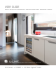
USER GUIDE u-line.com WELCOME TO U-LINE Congratulations on your U-Line purchase. Your product comes from a company with over five decades and three generations of premium modular ice making, refrigeration, and wine preservation experience. U-Line continues to be the American leader, delivering versatility and flexibility for multiple applications including residential, light commercial, outdoor and marine use.
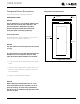
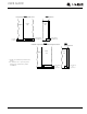
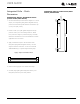
USER GUIDE u-line.com SAFETY • INSTALLATION & INTEGRATION • OPERATING INSTRUCTIONS • MAINTENANCE • SERVICE Integrated Panel Dimensions Integrated Frame Dimensions Metric measurements rounded and optimized. BACK SURFACE MUST HAVE AMPLE FLAT SURFACE TO MOUNT OVERLAY FRAME FLAT AND WITHOUT INTERFERENCE 3/4" INTEGRATED FRAME (20 mm) 17-5/8" (445 mm) NOTICE Due to differences in surrounding cabinetry the panel may not perfectly align with door.
USER GUIDE u-line.com SAFETY • INSTALLATION & INTEGRATION • OPERATING INSTRUCTIONS • MAINTENANCE • SERVICE HANDLELESS INTEGRATED FRAME 3. Prepare the insert(s) that will back up the handleless The following procedure is designed to provide a finished, design. Wooden Insert – Cut 1/8" (3 mm) thick handleless frame for an 18" (45 mm) door that seamlessly wooden insert(s) to the appropriate dimensions below. integrates with its surrounding cabinetry.
USER GUIDE u-line.com SAFETY • INSTALLATION & INTEGRATION • OPERATING INSTRUCTIONS • MAINTENANCE • SERVICE Handleless Integrated Frame Dimensions 1/8" (3 mm) Top Design 1/4" (6 mm) 7/8" (22 mm) Ref.
USER GUIDE u-line.com SAFETY • INSTALLATION & INTEGRATION • OPERATING INSTRUCTIONS • MAINTENANCE • SERVICE EXTENDED INTEGRATED FRAME NOTICE Due to differences in surrounding cabinetry the panel may not perfectly align with door. The procedure below is designed to provide a finished panel that seamlessly integrates with surrounding cabinetry. Panel Preparation An extended integrated panel can be used to maintain alignment with an adjacent extended cabinet height or a reduced toe-kick/grille application.
USER GUIDE u-line.com SAFETY • INSTALLATION & INTEGRATION • OPERATING INSTRUCTIONS • MAINTENANCE • SERVICE Front Side Integrated Panel/Integrated Frame Integrated Panel U-Line Unit Cabinet U-Line Unit 3-5/16" (89 mm) to 4-5/16" (114 mm) > 3-5/16" (> 89 mm) 3-5/16" (89 mm) to 4-5/16" (114 mm) Floor Front Side Extended Integrated Panel/Extended Integrated Frame U-Line Unit Cabinet * Panel can extend beyond the door frame.
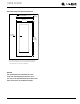
USER GUIDE u-line.com SAFETY • INSTALLATION & INTEGRATION • OPERATING INSTRUCTIONS • MAINTENANCE • SERVICE Extended Integrated Frame Dimensions BACK SURFACE MUST HAVE AMPLE FLAT SURFACE TO MOUNT INTEGRATED FRAME FLAT AND WITHOUT INTERFERENCE 3/4" (20 mm) 17-5/8" (445 mm) 2-3/4" MIN (70 mm MIN) 30.0" 33-7/8" (762 mm 860 mm)* Integrated Frame * A minimum of 1" (25 mm) is required from the floor to the bottom of the extended integrated panel/frame for proper ventilation.
USER GUIDE u-line.com SAFETY • INSTALLATION & INTEGRATION • OPERATING INSTRUCTIONS • MAINTENANCE • SERVICE 1. Use the dimensions provided in the diagram to cut and shape your integrated grille (plinth strip/base fascia) 3-5/16" (84 mm) 1" (25 mm) PREPARE AND INSTALL INTEGRATED GRILLE (PLINTH STRIP/BASE FASCIA) INTEGRATED GRILLE (PLINTH STRIP/BASE FASCIA) DIMENSIONS 1-9/16" (40 mm) Integrated Grille - Plinth Dimensions panel. Recommended panel thickness is between 1/4" (6 mm) and 3/8" (9 mm).
USER GUIDE u-line.com SAFETY • INSTALLATION & INTEGRATION • OPERATING INSTRUCTIONS • MAINTENANCE • SERVICE Integrated Panel Installation 1. Fully open door. NOTICE It is important to ensure that all drilled holes are drilled to the correct depth in order to avoid splits in the wood when hardwood is installed. 2. Starting at corner, pull gasket away from door. 8. Locate 6 of the #6x 1-1/2" (38 mm) screws provided with your unit. 3. Continue to pull gasket free from gasket channel. 9.
USER GUIDE u-line.com SAFETY • INSTALLATION & INTEGRATION • OPERATING INSTRUCTIONS • MAINTENANCE • SERVICE Grille - Plinth Installation REMOVING AND INSTALLING GRILLE (PLINTH STRIP/BASE FASCIA) ! WARNING Disconnect electric power to the unit before removing the grille (plinth strip/base fascia). When using the unit, the grille (plinth strip/base fascia) must be installed. ! WARNING DO NOT touch the condenser fins. The condenser fins are SHARP and can be easily damaged.