USER GUIDE SAFETY • INSTALLATION & INTEGRATION • OPERATING INSTRUCTIONS • MAINTENANCE • SERVICE RIGHT PRODUCT. RIGHT PLACE. RIGHT TEMPERATURE. SINCE 1962.
USER GUIDE u-line.
USER GUIDE u-line.com WELCOME TO U-LINE Congratulations on your U-Line purchase. Your product comes from a company with over five decades and three generations of premium modular ice making, refrigeration, and wine preservation experience. U-Line continues to be the American leader, delivering versatility and flexibility for multiple applications including residential, light commercial, outdoor and marine use.
USER GUIDE u-line.com SAFETY • INSTALLATION & INTEGRATION • OPERATING INSTRUCTIONS • MAINTENANCE • SERVICE Safety and Warning NOTICE Please read all instructions before installing, operating, or servicing the appliance.
USER GUIDE u-line.com SAFETY • INSTALLATION & INTEGRATION • OPERATING INSTRUCTIONS • MAINTENANCE • SERVICE Disposal and Recycling ! DANGER RISK OF CHILD ENTRAPMENT. Before you throw away your old refrigerator or freezer, take off the doors and leave shelves in place so children may not easily climb inside.
USER GUIDE u-line.com SAFETY • INSTALLATION & INTEGRATION • OPERATING INSTRUCTIONS • MAINTENANCE • SERVICE Environmental Requirements This model is intended for indoor/interior applications only and is not to be used in installations that are open/ exposed to natural elements. This unit is designed to operate between 50°F (10°C) and 100°F (38°C). Higher ambient temperatures may reduce the unit’s ability to reach low temperatures and/or reduce ice production on applicable models.
USER GUIDE u-line.com SAFETY • INSTALLATION & INTEGRATION • OPERATING INSTRUCTIONS • MAINTENANCE • SERVICE Electrical ! WARNING SHOCK HAZARD — Electrical Grounding Required. Never attempt to repair or perform maintenance on the unit until the electricity has been disconnected. Never remove the round grounding prong from the plug and never use a two-prong grounding adapter.
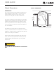
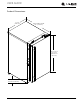
USER GUIDE u-line.com SAFETY • INSTALLATION & INTEGRATION • OPERATING INSTRUCTIONS • MAINTENANCE • SERVICE Cutout Dimensions CUTOUT DIMENSIONS PREPARE SITE Your U-Line product has been designed exclusively for a built-in installation. When built-in, your unit does not Preferred location for drain, water line and receptacle is in adjacent 5/8" cabinet. (16 mm) require additional air space for top, sides, or rear. However, the front grille must NOT be obstructed.
USER GUIDE u-line.
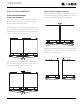
USER GUIDE u-line.com SAFETY • INSTALLATION & INTEGRATION • OPERATING INSTRUCTIONS • MAINTENANCE • SERVICE Side-by-Side Installation OTHER SITE REQUIREMENTS Side-by-Side Installation Hinge-by-Hinge Installation (Mullion) When installing two units hinge-by-hinge, 13/16" (22 mm) is required for integrated models. Additional space may be needed for any knobs, pulls or handles installed.
USER GUIDE u-line.com SAFETY • INSTALLATION & INTEGRATION • OPERATING INSTRUCTIONS • MAINTENANCE • SERVICE Water Hookup PREPARE PLUMBING ! CAUTION Please use the braided stainless steel water supply line Do not use any plastic water supply line. The line which comes attached. The water line is fitted with a is under pressure at all times. Plastic may crack standard 1/4" (6.35 mm) compression fitting. or rupture with age and cause damage to your home.
USER GUIDE u-line.com SAFETY • INSTALLATION & INTEGRATION • OPERATING INSTRUCTIONS • MAINTENANCE • SERVICE 4. Turn on water and check for leaks. 5. Route water supply line in cable clamp and secure with screw.
USER GUIDE u-line.com SAFETY • INSTALLATION & INTEGRATION • OPERATING INSTRUCTIONS • MAINTENANCE • SERVICE Drain GRAVITY DRAIN Model numbers including “-00” or “-07” do not include a factory installed drain pump. Normal Proper Drain Model numbers including “-40” or “-47” include a factory installed drain pump.
USER GUIDE u-line.com SAFETY • INSTALLATION & INTEGRATION • OPERATING INSTRUCTIONS • MAINTENANCE • SERVICE FACTORY INSTALLED DRAIN PUMP If your drain line will run up to a stand pipe, disposal or Y-Branch Tailpiece P60 Pump Required Air Gap (Optional Hook-Up) spigot assembly, or does not otherwise meet the requirements for a gravity drain, you may have ordered a pre-installed U-Line P60 drain pump.
USER GUIDE u-line.com SAFETY • INSTALLATION & INTEGRATION • OPERATING INSTRUCTIONS • MAINTENANCE • SERVICE Drain Pump NOTICE PLEASE READ this instruction completely before attempting to install or operate the unit. Improper hook-up can result in substantial property damage! If you are unsure of your ability to safely connect the drain pump to the INCLUDED IN KIT: 1. 1x S-shaped Drain Tube 1 2. 1x Straight Drain Tube (Not used) 2 3. 1x Vent Tube 3 unit, consult a licensed plumber for assistance.
USER GUIDE u-line.com SAFETY • INSTALLATION & INTEGRATION • OPERATING INSTRUCTIONS • MAINTENANCE • SERVICE 8 Wiring Plug Ground Terminal Discharge Tube Connector Drain Tube Connector Vent Tube Connector Pump Assembly Note: Slide clamp on hose end before installing hose. Do not tighten clamp until pump and hoses have been installed. 4. Install the 3 hoses and hose clamps to the pump assembly as shown below. Do not tighten clamps at this time.
USER GUIDE u-line.com SAFETY • INSTALLATION & INTEGRATION • OPERATING INSTRUCTIONS • MAINTENANCE • SERVICE ! CAUTION 8. Route the vent tube up the back of the unit, next to the insulated tubes. When working with tools inside of unit, be Secure vent tube vertical careful so as not to nick or damage any to the insulated tubes refrigerant lines/pipes or wires. using plastic tie wraps. ! WARNING 9.
USER GUIDE u-line.com SAFETY • INSTALLATION & INTEGRATION • OPERATING INSTRUCTIONS • MAINTENANCE • SERVICE Anti-Tip Bracket SIDE MOUNT Left Hinged Cabinet Right Hinged Cabinet ! CAUTION The anti-tip bracket must be installed to prevent the unit from tipping when doors are fully opened or excess weight is placed on the front of the unit. The anti-tip bracket has multiple mounting options. Mounting will depend on your particular cabinet configuration. Locate 3 #8x5/8" screws included with your unit.
USER GUIDE u-line.com SAFETY • INSTALLATION & INTEGRATION • OPERATING INSTRUCTIONS • MAINTENANCE • SERVICE General Installation 1. Plug in the power/electrical cord. 1. Use a level to confirm the unit is level. Level 2. Gently push the unit into position. Be careful not to should be placed along top edge and side INSTALLATION 1 entangle the cord or water and drain lines. edge as shown. 3. Re-check the leveling, from front to back and side to side. Make any necessary adjustments.
USER GUIDE u-line.com SAFETY • INSTALLATION & INTEGRATION • OPERATING INSTRUCTIONS • MAINTENANCE • SERVICE INTEGRATED GRILLE (PLINTH STRIP/BASE FASCIA) DIMENSIONS 3-5/16" to 4-5/16" (84 mm to 110 mm) Integrated Grille - Plinth Dimensions PREPARE AND INSTALL INTEGRATED GRILLE (PLINTH STRIP/BASE FASCIA) panel. Recommended panel thickness is between 1/4" (6 mm) and 3/8" (9 mm). Height will vary from 3-5/16" 1" (25 mm) shape your integrated grille (plinth strip/base fascia) 1-9/16" (40 mm) 1.
USER GUIDE u-line.com SAFETY • INSTALLATION & INTEGRATION • OPERATING INSTRUCTIONS • MAINTENANCE • SERVICE Grille - Plinth Installation Installing the grille (plinth strip/base fascia) REMOVING AND INSTALLING GRILLE (PLINTH STRIP/BASE FASCIA) 1. Align slots in grille (plinth strip/base fascia) rail with ! WARNING Disconnect electrical current to the unit before removing the grille (plinth strip/base fascia). When using the unit, the grille (plinth strip/base fascia) must be installed.
USER GUIDE u-line.com SAFETY • INSTALLATION & INTEGRATION • OPERATING INSTRUCTIONS • MAINTENANCE • SERVICE Door Stop 3. Once cover is removed, slide hinge pin into hole as shown. Pin should slide into place, stopping the door at Your U-Line unit was shipped to you with the optional 90° 90°; if the pin does not go into the hole shown, hold pin. the door less than 90° open and try again. Your unit’s door(s) will open 115° straight from the factory.
USER GUIDE u-line.com SAFETY • INSTALLATION & INTEGRATION • OPERATING INSTRUCTIONS • MAINTENANCE • SERVICE Door Adjustments DOOR ALIGNMENT AND ADJUSTMENT Align and adjust the door if it is not level or is not sealing properly. If the door is not sealed, the unit may not cool T-25 Torx Screw properly, or excessive frost or condensation may form in the interior. NOTICE Properly aligned, the door’s gasket should be firmly in contact with the cabinet all the way T-25 Torx Screw around the door (no gaps).
USER GUIDE u-line.com SAFETY • INSTALLATION & INTEGRATION • OPERATING INSTRUCTIONS • MAINTENANCE • SERVICE 3. Using T-25 Torx bit loosen screw #1 and remove screw #2 on top and bottom hinge. Slide and remove the door from unit. Completely remove screw #1 on top and bottom. 2 1 4. Remove caps from screw heads on opposite side (2 on top and 2 on bottom). Using #2 Phillips bit remove the 4 underlying screws. Reinstall the screws and caps on the opposite side. 5.
USER GUIDE u-line.com SAFETY • INSTALLATION & INTEGRATION • OPERATING INSTRUCTIONS • MAINTENANCE • SERVICE First Use All U-Line controls are preset at the factory. Initial startup requires no adjustments. NOTICE U-Line recommends discarding the ice produced during the first two to three hours of operation to avoid possible dirt or scale that may dislodge from the water line. When plugged in, the unit will begin operating under the factory default setting.
USER GUIDE u-line.com SAFETY • INSTALLATION & INTEGRATION • OPERATING INSTRUCTIONS • MAINTENANCE • SERVICE Control Operation Zone Toggle Up Select ICE PRODUCTION Power U-Select Lighting Down CONTROL FUNCTION GUIDE FUNCTION COMMAND DISPLAY/OPTIONS OFF Press and hold Display will count down from 5 to off. ON Press and release Unit will come on immediately. Adjust lighting Press to adjust lighting Press or to set low, medium or high.
USER GUIDE u-line.com SAFETY • INSTALLATION & INTEGRATION • OPERATING INSTRUCTIONS • MAINTENANCE • SERVICE Energy Saver Mode 3000 Series - Customer Menu Up Up Energy Saver Mode Indicator Select WELCOME TO THE CUSTOMER MENU. USE UP/DOWN ARROWS TO SCROLL SETTINGS. Select ICE PRODUCTION (12m remaining) Down Down 1. To access the Customer Menu hold for 5 seconds.
USER GUIDE u-line.com SAFETY • INSTALLATION & INTEGRATION • OPERATING INSTRUCTIONS • MAINTENANCE • SERVICE Languages 2. Press . The current setting will begin to flash. Up Select RETURN TO MENU LANGUAGES ENGLISH 3. Press or to select a different level. 4. Press to confirm your choice. Down The U-Line 3000 Series of models supports a number of display languages including English, Spanish, French, Fahrenheit / Celsius Up Select German and Italian.
USER GUIDE u-line.com SAFETY • INSTALLATION & INTEGRATION • OPERATING INSTRUCTIONS • MAINTENANCE • SERVICE To activate Silent Mode: Clean Cycle Up Select RETURN TO MENU CLEAN CYCLE CLEAN? 1. Press 2. Press to select “Silence?”. . Silent Mode will now begin. To cancel Silent Mode: Down A clean cycle can be initiated through this menu. Once the cleaning cycle starts, the cycle cannot be stopped until 1. Press to select “Cancel?”. 2. Press . Silent Mode will end. complete.
USER GUIDE u-line.com SAFETY • INSTALLATION & INTEGRATION • OPERATING INSTRUCTIONS • MAINTENANCE • SERVICE Help Up Select RETURN TO MENU Help Model 3018CLR 1-800-779-2547 Down To access the Help Menu, select “Help” from the Customer Menu. Press or to scroll through available information. To return to the Customer Menu, press “Return to Menu” and press to select to confirm.
USER GUIDE u-line.com SAFETY • INSTALLATION & INTEGRATION • OPERATING INSTRUCTIONS • MAINTENANCE • SERVICE Ice Your clear ice machine is pre-set to produce ice between the optimal dimensions illustrated below: ICE CUBE THICKNESS ADJUSTMENT Cube Types NOTICE Ice thickness adjustment should only be made 1/4" TO 1/2" (6.4 mm to 12.7 mm) DIMPLE 1/16" TO 1/8" (1.6 mm to 3.2 mm) ICE BRIDGE one increment at a time. Allow ice maker production to stabilize for 24 hours before rechecking ice thickness.
USER GUIDE u-line.com SAFETY • INSTALLATION & INTEGRATION • OPERATING INSTRUCTIONS • MAINTENANCE • SERVICE ICE ADJUST Up Select RETURN TO MENU ICE ADJUST ICE ADJUST = 0 Down Adjust ice thickness as follows: 1. Press and and hold for 5 seconds to enter the Customer Menu. 2. Press 3. Press 4. Press to select “Ice Adjust”. . The selection will begin to flash. to make the ice thicker or thinner. Press to make the ice to confirm your choice.
USER GUIDE u-line.com SAFETY • INSTALLATION & INTEGRATION • OPERATING INSTRUCTIONS • MAINTENANCE • SERVICE L Sabbath Mode 1 2 3 4 5 6 7 Up Select Down U-Line Clear Ice Machine models are Star-K certified and can be used during the Sabbath. View a full list of Star-K certified U-Line units at www.star-k.org. To prepare the unit for the Sabbath: 1. Press and hold the until the unit turns off. 2.
USER GUIDE u-line.com SAFETY • INSTALLATION & INTEGRATION • OPERATING INSTRUCTIONS • MAINTENANCE • SERVICE Airflow and Product Loading NOTICE The unit requires proper airflow to perform at its highest efficiency. Do not block the front grille at any time, or the unit will not perform as expected. Do not install the unit behind a door.
USER GUIDE u-line.com SAFETY • INSTALLATION & INTEGRATION • OPERATING INSTRUCTIONS • MAINTENANCE • SERVICE Cleaning EXTERIOR CLEANING Integrated Models To clean integrated panels, use household cleaner per the cabinet manufacturer’s recommendations. Stainless Models Stainless door panels and handles can discolor when exposed to chlorine gas, pool chemicals, saltwater or cleaners with bleach.
USER GUIDE u-line.com SAFETY • INSTALLATION & INTEGRATION • OPERATING INSTRUCTIONS • MAINTENANCE • SERVICE Use only U-Line Ice Machine Cleaner (Part No. 5. Re-install the standpipe into the water trough. 37050), available from your dealer or direct from your local parts distributor. To locate a parts distributor near you, visit www.u-line.com. It is a violation of federal law to use this solution in a manner inconsistent with its labeling.
USER GUIDE u-line.com SAFETY • INSTALLATION & INTEGRATION • OPERATING INSTRUCTIONS • MAINTENANCE • SERVICE 9. When water begins flowing over the evaporator (approximately 3 minutes), pour 1 packet of CLR cleaner into the water trough. The cleaning process will last approximately 45 minutes. 10.Dilute 1 tablespoon (15 ml) bleach in 1 gallon (3.8 liters) of warm water. Apply this solution to the entire inside of the storage area. Then rinse thoroughly with water.
USER GUIDE u-line.com SAFETY • INSTALLATION & INTEGRATION • OPERATING INSTRUCTIONS • MAINTENANCE • SERVICE Cleaning Condenser INTERVAL - EVERY SIX MONTHS To maintain operational efficiency, keep the front grille (plinth strip/base fascia) free of dust and lint, and clean the condenser when necessary. Depending on environmental conditions, more or less frequent cleaning may be necessary. ! WARNING Disconnect electric current to the unit before cleaning the condenser.
USER GUIDE u-line.com SAFETY • INSTALLATION & INTEGRATION • OPERATING INSTRUCTIONS • MAINTENANCE • SERVICE Extended Non-Use VACATION/HOLIDAY, PROLONGED SHUTDOWN For questions regarding winterization, please The following steps are recommended for periods of call U-Line at +1.800.779.2547. extended non-use: 1. Remove all consumable content from the unit. 2. Disconnect the power cord from its outlet/socket and leave it disconnected until the unit is returned to service.
USER GUIDE u-line.com SAFETY • INSTALLATION & INTEGRATION • OPERATING INSTRUCTIONS • MAINTENANCE • SERVICE Troubleshooting • Compressor: The compressor makes a hum or pulsing sound that may be heard when it operates. BEFORE CALLING FOR SERVICE If you think your U-Line product is malfunctioning, read the CONTROL OPERATION section to clearly understand the function of the control.
USER GUIDE u-line.com SAFETY • INSTALLATION & INTEGRATION • OPERATING INSTRUCTIONS • MAINTENANCE • SERVICE Problem Possible Cause and Remedy No Ice Production Ensure water is being supplied to the unit. Verify the ice making unit is turned on. Not Enough Ice Ensure the condenser coil is clean and free of any dirt or lint buildup. Water in Bin Ensure the unit is plugged in. Check if the drain is restricted. Ensure drain is free of foreign debris and hose is not kinked or twisted.
USER GUIDE u-line.com SAFETY • INSTALLATION & INTEGRATION • OPERATING INSTRUCTIONS • MAINTENANCE • SERVICE U-Line Corporation | Limited Warranty 1. U-Line Corporation (“U-Line”) warrants each U-Line product to be free from defects in materials and workmanship for a period of one year (two years on Modular 3000 Series) from the date of installation.
USER GUIDE u-line.com SAFETY • INSTALLATION & INTEGRATION • OPERATING INSTRUCTIONS • MAINTENANCE • SERVICE defective parts be returned, at your expense, to ULine’s factory in Milwaukee, Wisconsin, for inspection. Any action by you for breach of warranty must be commenced within one year after the applicable warranty period. 8.