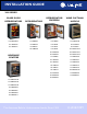
INSTALLATION GUIDE ® 2000 SERIES REFRIGERATORS REFRIGERATOR/ FREEZERS WINE CAPTAIN® MODELS U-2175RCGOL-00 U-2175RFB-00 U-2115RB-00 U-2115WCOL-00 U-2175RCGS-00 U-2175RFS-00 U-2115RS-00 U-2115WCS-00 U-2175RCGS-01 U-2175RFS-01 U-2115RS-01 U-2115WCS-01 U-2175RFW-00 U-2115RS-02 U-2175WCCOL-00 U-2115RSOD-00 U-2175WCCOL-02 U-2115RSOD-01 U-2175WCCOL-60 U-2115RW-00 U-2175WCCS-00 U-2175RCB-00 U-2175WCCS-01 U-2175RCB-02 U-2175WCCS-02 U-2175RCS-00 U-2175WCCS-13 U-2175RCS-01 U-2175WCCS-
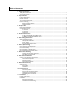
Table of Contents 1 - Safety Precautions Safety Alert Definitions.........................................................................................................................................1 General Precautions ..............................................................................................................................................1 2 - Inspect & Plan Product Registration ........................................................................................................
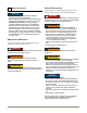
General Precautions 1 Safety Precautions Use this appliance for its intended purpose only. Follow these general precautions with those listed throughout this guide: NOTICE • PLEASE READ all instructions before installing, operating, or servicing the appliance. • Proper installation procedures must be followed when completing an installation or relocation of a unit. An INSTALLATION GUIDE for the unit, providing complete installation information, is available from U-Line Corporation direct.
Tools / Material Required 2 Inspect & Plan • Screwdrivers — slotted and Phillips head (Models ending in OL Only) • 3/4" overlay frame material • Cutting Tools Product Registration • Drill & Drill Bits You have received a carton containing your U-Line Refrigerator, Refrigerator Freezer, Beverage Center or Wine Captain® unit with a package inside containing a Use and Care Guide, a Product Registration Card, and a water line kit.
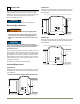
2175 Series 3 Prepare Site Your U-Line product has been designed for either free-standing or built-in installation. When built-in, your unit does not require additional air space for top, sides, or rear. However, the front grille must NOT be obstructed and clearance is required for an electrical connection in the rear. Follow the cut-out drawing The 24-1/4" width allows 1/4" for ease in installation and removal of the unit. 24" is the cabinet depth in most installations.
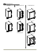
2115R, 2115WC(OL) & 2175RC Series 4 Product Dimensions 2115R Series 2115WC / 2115WCOL Series 21175RC/RCG/RF Series 23-1/4" 23-1/16" 23-1/4" 34-1/8" 34-1/8" 3-13/16" 15" 3-13/16" 34-1/8" 15" 3-13/16" 2115R Black / White Models 24" 2115WCS Stainless Steel Models 2175R(C)(F) Black and White Models 23-1/2" 23-1/8” 23-1/16" 34-1/8" 34-1/8" 34-1/8" 3-13/16" 3-13/16" 15" 15" 2115RS Stainless & Outdoor Models 2115WCOL Wood Overlay Models *Not Including Wood Overlay Panel 3-13/16" 24" 21
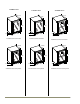
2175BEV, 2175WC & 2275ZWC Series 2175BEVC Series 2175WCC Series 23-1/4" 2175BEVCS Stainless Steel Models 24" 2175BEVCOL Wood Overlay Models 24" 2275ZWCS Stainless Steel Model 22-5/8" 22-5/8" 34-1/8" 34-1/8" 34-1/8" 23-15/16" 3-13/16" 2175WCCS Stainless Steel Models 22-5/8" 3-13/16" 34-1/8" 34-1/8" 3-13/16" 23-15/16" 23-1/4" 23-1/4" 34-1/8" 3-13/16" 2275ZWC Series 3-13/16" 24" 2175WCCOL Wood Overlay Models u-line.
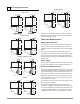
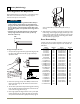
5 Door Swing Dimensions 2175WC Models Wall 2115R Models Wall 2" Min. Wall Wall 1/4" Min. 2" Min. 21" 21" 21" 21" 25-1/2" 90 Door Swing 16-1/2" 90 Door Swing 25-1/2" 90 Door Swing Black, White and Wood Overlay 16-1/2" Stainless Steel 90 Door Swing Stainless Models Black and White Models 2115WC Models Wall Wall 1/4" Min. Units have a zero clearance for the door to open 90°. Stainless Steel models require 2-1/8" door clearance to accommodate the handle if installed next to a wall.
6 Doors (Self-Closing) Door Alignment and Adjustment Align and adjust the door if it is not level, or is not sealing properly. If the door is not sealed the unit may not cool properly, or excessive frost may form in the interior. NOTICE • Properly aligned, the door’s gasket should be firmly in contact with the cabinet all the way around the door (no gaps). Carefully examine the door’s gasket to ensure that it is firmly in contact with the cabinet.
Reversing Black or White Doors Remove Door 3 1 2 1. Hold door to keep it from falling. 2. Remove hinge screw pin (1) from top hinge using a Phillips screwdriver. 3. Remove door by tilting forward and lifting door off bottom hinge closer inserts. 4. Reinstall hinge screw pin (1) into top hinge using a Phillips screwdriver. • The hinge hardware will be removed and reinstalled on the opposite side of the cabinet. Remove hole plugs.
Remove preexisting bottom hinge. Reversing Stainless Steel Glass Doors 1. Remove the preexisting bottom hinge (three screws) (2). Remove Door Reinstall hinge to top opposite. 1. Install the hinge just removed from the bottom to the TOP opposite side of the cabinet (three screws) (2). 3 1 Reinstall Hole Plugs. 1. Install plastic screw plugs (three each, top and bottom) (3) into holes where hinge hardware was removed. 2 1. Hold door to keep it from falling. 1 2.
3. Grasp outer edge of stainless frame and firmly press inside edge of glass in while pulling stainless frame in opposite direction. 3. Swing door into frame. 4. Install screws removed in “Remove Stainless Frame” step 1 to top of door, opposite handle. 5. Install pivot plat to bottom of door, opposite of handle, using hardware removed in “Remove Stainless Frame” step 2. Arrange pivot plate so the flat edge is against the edge of the door.
Remove existing bottom hinge. 1. Remove the existing bottom hinge (three screws) (2). Reinstall hinge to top opposite. 1. Install the hinge just removed from the bottom to the TOP opposite side of the cabinet (three screws) (2). Reinstall Hole Plugs. 1. Install plastic screw plugs (three each, top and bottom) (3) into holes where hinge hardware was removed. Install Door. 1. Hold door upright and tilted forward. 2. Lift door on to bottom hinge closer inserts. 3. Tilt door forward into position. 4.
Staining and final finish application: 7 Wood Trim Finishing NOTICE ! CAUTION To prevent permanent damage to the inner liner of the unit, the wire rack wood trim MUST be removed from the unit for staining and/or finishing. Allow stain/finish to dry thoroughly (at least 24 hours) in accordance with the stain/finish manufacturer’s instructions, prior to reinstalling the wood trim inside the cabinet of the unit.
3. Remove the two outside screws holding door handle. Slightly separate door handle from door. 8 Door Panel Installation Custom 1/4'' Thick Door Panel Insert 4. Pull handle up and off. Door Panel Preparation A custom door panel may be inserted into the doorframe. Custom door panels can be flat or raised, as long as the maximum panel thickness, where inserted into the door reveal (channel), is no more than 1/4" thick. For raised panels, the depth of the reveal is 1/4" on all four sides.
Hook and Loop Fastener Mount 9 Wood Grille Overlay Grille Overlay Your model’s grille is designed to accept a wood grille overlay. An overlay may be used to compliment a door overlay and provides a seamless look for your surrounding decor. Follow the instructions below to prepare and install your grille overlay. Be sure to read over this chapter completely before beginning. Preparation You may also mount your overlay to your grille using hook and loop type fasteners.
1/4 1/2 3-3/32 2-1/8 11/64 u-line.
16 1/4 1/2 3-3/32 2-1/8 11/64 u-line.com 14-7/8 10-5/8 13-7/8 .
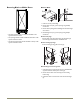
1. Use the following instructions to create or have a wood overlay panel created for you Wine Captain® or beverage Center model as shown below. 10 Overlay Frame Frame Preparation 2115WCOL 2175WCCOL & 2175BEVCOL Models Only 2. Drill holes for pivot pins, upper door hinge and lower door hinge as shown. An overlay frame covers the door frame to give a built-in appearance. Appropriate hardware and a copy of these instructions will be included with the unit.
Prepare the New Overlay Panel NOTICE The overlay door panel must not weigh more than 20 lbs. The thickness of the door panel must be 3/4". 1. Place a towel, or similar, soft non-marking material out on a flat clean surface. Be sure the material is large enough to have the wood panel not touch the hard mating surface. 2. Lay the wood panel out with the front side of the wood facing down. 3. Cut the foam tape in to four pieces, two pieces the width of the overlay and two pieces the height of the overlay. 4.
Assembling Door to Cabinet 8. Starting at the corners and working toward the center, push the door gasket back into place. Make sure the gasket is fully seated on all four sides and corners. DOOR FRAME TAPE 9. Check the closure assembly on the bottom hinge to be sure it is seated correctly in the bosses in the hinge. TOP OF OVERLAY BOTTOM OF OVERLAY ULIN_0418_A 6. Use the door frame holes as a guide to drill pilot holes for the #6x1" pan head screws.
Installation 11 11 Installation 1. Plug in the powercord. Leveling Information 2. Gently push the unit into position. Be careful not to kink the water supply line or entangle the electrical cord. It is recommended that the unit is level. 3. Re-check the leveling, from front to back and side to side. Make any necessary adjustments. The unit’s top surface should be approximately 1/8" below the countertop. 13. Use a level to check the levelness of the unit from front to back and from side to side.
INSTALLATION GUIDE ® PRODUCT INFORMATION Complete Installation Guides, Use and Care Guides, Specifications & Features and Benefits, CAD Drawings, Overlay Panel/Frame and Toe-Kick Specifications and Instructions, Compliance Documentation and Applicable Energy Guides are available for reference and download at u-line.com. SERVICE INFORMATION Please consult your Use and Care Guide for troubleshooting information. Answers to Customer Frequently Asked Questions are available at u-line.