USER GUIDE SAFETY • INSTALLATION & INTEGRATION • OPERATING INSTRUCTIONS • MAINTENANCE • SERVICE RIGHT PRODUCT. RIGHT PLACE. RIGHT TEMPERATURE. SINCE 1962.
USER GUIDE u-line.
USER GUIDE u-line.com WELCOME TO U-LINE Congratulations on your U-Line purchase. Your product comes from a company with over five decades and three generations of premium modular ice making, refrigeration, and wine preservation experience. U-Line continues to be the American leader, delivering versatility and flexibility for multiple applications including residential, light commercial, outdoor and marine use.
USER GUIDE u-line.com SAFETY • INSTALLATION & INTEGRATION • OPERATING INSTRUCTIONS • MAINTENANCE • SERVICE Safety and Warning ! DANGER NOTICE This unit contains R600a (Isobutane) which is a Please read all instructions before installing, flammable hydrocarbon. It is safe for regular operating, or servicing the appliance. use. Do not use sharp objects to expedite defrosting.
USER GUIDE u-line.com SAFETY • INSTALLATION & INTEGRATION • OPERATING INSTRUCTIONS • MAINTENANCE • SERVICE Disposal and Recycling ! DANGER RISK OF CHILD ENTRAPMENT. Before you throw away your old refrigerator or freezer, take off the doors and leave shelves in place so children may not easily climb inside.
USER GUIDE u-line.com SAFETY • INSTALLATION & INTEGRATION • OPERATING INSTRUCTIONS • MAINTENANCE • SERVICE Environmental Requirements This model is intended for indoor/interior applications only and is not to be used in installations that are open/ exposed to natural elements. This unit is designed to operate between 50°F (10°C) and 100°F (38°C). Higher ambient temperatures may reduce the unit’s ability to reach low temperatures and/or reduce ice production on applicable models.
USER GUIDE u-line.com SAFETY • INSTALLATION & INTEGRATION • OPERATING INSTRUCTIONS • MAINTENANCE • SERVICE Electrical ! WARNING SHOCK HAZARD — Electrical Grounding Required. Never attempt to repair or perform maintenance on the unit until the electricity has been disconnected. Never remove the round grounding prong from the plug and never use a two-prong grounding adapter.
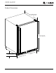
USER GUIDE u-line.com SAFETY • INSTALLATION & INTEGRATION • OPERATING INSTRUCTIONS • MAINTENANCE • SERVICE Cutout Dimensions PREPARE SITE Your U-Line product has been designed for either freestanding or built-in installation. When built-in, your unit does not require additional air space for top, sides, or rear. However, the front grille must NOT be obstructed, and clearance is required for an electrical connection in the rear. ! CAUTION Unit can NOT be installed behind a closed cabinet door.
USER GUIDE u-line.
USER GUIDE u-line.com SAFETY • INSTALLATION & INTEGRATION • OPERATING INSTRUCTIONS • MAINTENANCE • SERVICE Side-by-Side Installation Two units may be installed side-by-side. Cutout width for a side-by-side installation is the cutout dimension of a single unit times two. No trim kit is required. However, 1/4" (6 mm) of space 3. Place bracket over holes and attach to unit with two screws removed in step 2 using a T-25 Torx driver. Tighten screws fully. 4. Gently push units into position.
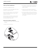
USER GUIDE u-line.com SAFETY • INSTALLATION & INTEGRATION • OPERATING INSTRUCTIONS • MAINTENANCE • SERVICE Anti-Tip Bracket 1. Slide unit out so screws on top of unit are easily accessible. 2. Remove the two screws from the opposite side of the hinge assembly using a T-25 Torx driver (see below). NOTE: 1224 models shown with four screw. 1215 models only have three screws, but same screws are used in both applications. 3.
USER GUIDE u-line.com SAFETY • INSTALLATION & INTEGRATION • OPERATING INSTRUCTIONS • MAINTENANCE • SERVICE General Installation INSTALLATION 1. Plug in the power/electrical cord. LEVELING INFORMATION 1. Use a level to 2. Gently push the unit into position. Be careful not to confirm the unit is entangle the cord. level. Level should be placed along top 3. Re-check the leveling, from front to back and side to edge and side edge side. Make any necessary adjustments. The unit’s top as shown.
USER GUIDE u-line.com SAFETY • INSTALLATION & INTEGRATION • OPERATING INSTRUCTIONS • MAINTENANCE • SERVICE Grille - Plinth Installation REMOVING AND INSTALLING GRILLE ! WARNING Disconnect electric power to the unit before removing the grille. When using the unit, the grille (plinth strip/base fascia) must be installed. ! WARNING DO NOT touch the condenser fins. The condenser fins are SHARP and can be easily damaged. Removing the grille 1. Disconnect power to the unit. 2. Loosen the two screws (1).
USER GUIDE u-line.com SAFETY • INSTALLATION & INTEGRATION • OPERATING INSTRUCTIONS • MAINTENANCE • SERVICE Door Swing Wall Wall 1/4" Min. (6 mm) 90 Door Swing 2-1/8" Min. (54 mm) 90 Door Swing Units have a zero clearance for the door to open 90°, when installed adjacent to cabinets. Stainless Steel and black and white models require 2-1/8" (54 mm) door clearance to accommodate the handle if installed next to a wall. Integrated models require 1/4" (6 mm) clearance if installed next to a wall.
USER GUIDE u-line.com SAFETY • INSTALLATION & INTEGRATION • OPERATING INSTRUCTIONS • MAINTENANCE • SERVICE Door Stop 3. On 24" models, a second pin is included for the bottom hinge. Repeat steps above for second hinge. Your U-Line unit was shipped to you with the optional 90° pin(s). (Models that are 15" wide include 1 pin. Models that are 24" wide include 2 pins.) The unit’s door will open NOTE: Threaded pin will be inserted from the bottom. freely without a fixed opening angle limitation.
USER GUIDE u-line.com SAFETY • INSTALLATION & INTEGRATION • OPERATING INSTRUCTIONS • MAINTENANCE • SERVICE Door Adjustments DOOR ALIGNMENT AND ADJUSTMENT Align and adjust the door if it is not level or is not sealing properly. If the door is not sealed, the unit may not cool properly, or excessive frost may form in the interior. NOTICE Properly aligned, the door’s gasket should be firmly in contact with the cabinet all the way around the door (no gaps).
USER GUIDE u-line.com SAFETY • INSTALLATION & INTEGRATION • OPERATING INSTRUCTIONS • MAINTENANCE • SERVICE 3. Remove bottom hinge from cabinet by removing three 4. Tighten three screws. screws. Support the door and hinge assembly and remove it from the cabinet. 5. Align flat edge of the hinge with the outer edge of the 4. Remove four screws from hinge holes on the opposite unit. side. Reinstall into holes where the hinge was removed. Take care not to scratch cabinet. 6. Tighten three screws. 5.
USER GUIDE u-line.com SAFETY • INSTALLATION & INTEGRATION • OPERATING INSTRUCTIONS • MAINTENANCE • SERVICE Free Standing Kit The free standing kit is an optional accessory. It is only used when unit is not installed in surrounding cabinetry. To install the kit: 1. Remove grille (see GRILLE-PLINTH INSTALLATION section). 3. Align front hole with hole in shell accessory, hole in base, and hole in grille. Tighten screw. 2.
USER GUIDE u-line.com SAFETY • INSTALLATION & INTEGRATION • OPERATING INSTRUCTIONS • MAINTENANCE • SERVICE First Use All U-Line controls are preset at the factory. Initial startup requires no adjustments. NOTICE U-Line recommends allowing the unit to run overnight before loading with product. When plugged in, the unit will begin operating under the factory default settings. If the unit was turned off during installation, simply press and the unit will immediately switch on.
USER GUIDE u-line.com SAFETY • INSTALLATION & INTEGRATION • OPERATING INSTRUCTIONS • MAINTENANCE • SERVICE Control Operation Up Down Not Alert Light Power Used LED CONTROL FUNCTION GUIDE FUNCTION COMMAND DISPLAY/OPTIONS ON/OFF Press and release Unit will immediately turn ON or OFF.
USER GUIDE u-line.com SAFETY • INSTALLATION & INTEGRATION • OPERATING INSTRUCTIONS • MAINTENANCE • SERVICE L Sabbath Mode 1 2 3 4 5 6 This unit is Star-K certified and offers a Sabbath mode. Sabbath mode disables system responses to user initiated activities and all external functions, including lighting, display and audible alarms. The unit will still maintain internal temperatures and set points. View a full list of Star-K certified U-Line units at www.star-k.org. To enable Sabbath Mode: 1.
USER GUIDE u-line.com SAFETY • INSTALLATION & INTEGRATION • OPERATING INSTRUCTIONS • MAINTENANCE • SERVICE Airflow and Product Loading NOTICE The unit requires proper airflow to perform at its highest efficiency. Do not block the front grille, or the unit will not perform as expected. Do not install the unit behind a door. When loading your unit, leave space between the evaporator and product loaded. Anything in direct contact with the evaporator is subject to freezing.
USER GUIDE u-line.com SAFETY • INSTALLATION & INTEGRATION • OPERATING INSTRUCTIONS • MAINTENANCE • SERVICE Interior Shelves NOTICE REMOVING AND INSTALLING INTERIOR SHELVES Make sure the shelves are inserted fully into the unit. The edge strip toward the rear prevents cans and bottles from freezing against the cold evaporator. 3 1 2 For models equipped with glass shelves having recessed shelf supports, remove the shelves as follows: 1.
USER GUIDE u-line.com SAFETY • INSTALLATION & INTEGRATION • OPERATING INSTRUCTIONS • MAINTENANCE • SERVICE Cleaning If any surface discoloring or rusting appears, clean it EXTERIOR CLEANING and a nonabrasive cloth. Always clean with the grain. Vinyl Clad (Black or White) Always finish with Claire® Stainless Steel Polish and Clean surfaces with a mild detergent and warm water solution. Do not use solvent-based or abrasive cleaners.
USER GUIDE u-line.com SAFETY • INSTALLATION & INTEGRATION • OPERATING INSTRUCTIONS • MAINTENANCE • SERVICE High ambient temperature and excessive humidity can also produce frost. ! CAUTION DO NOT use an ice pick or other sharp instrument to help speed up defrosting. These instruments can puncture the inner lining or damage the cooling unit. DO NOT use any type of heater to defrost. Using a heater to speed up defrosting can cause personal injury and damage to the inner lining.
USER GUIDE u-line.com SAFETY • INSTALLATION & INTEGRATION • OPERATING INSTRUCTIONS • MAINTENANCE • SERVICE Cleaning Condenser INTERVAL - EVERY SIX MONTHS To maintain operational efficiency, keep the front grille free of dust and lint, and clean the condenser when necessary. Depending on environmental conditions, more or less frequent cleaning may be necessary. ! WARNING Disconnect electric power to the unit before cleaning the condenser. ! WARNING DO NOT touch the condenser fins.
USER GUIDE u-line.com SAFETY • INSTALLATION & INTEGRATION • OPERATING INSTRUCTIONS • MAINTENANCE • SERVICE Extended Non-Use VACATION/HOLIDAY, PROLONGED SHUTDOWN The following steps are recommended for periods of extended non-use: 1. Remove all consumable content from the unit. 2. Disconnect the power cord from its outlet/socket and leave it disconnected until the unit is returned to service. 3. If ice is on the evaporator, allow ice to thaw naturally. 4. Clean and dry the interior of the unit.
USER GUIDE u-line.com SAFETY • INSTALLATION & INTEGRATION • OPERATING INSTRUCTIONS • MAINTENANCE • SERVICE Troubleshooting • Evaporator: Refrigerant flowing through an evaporator may sound like boiling liquid. BEFORE CALLING FOR SERVICE If you think your U-Line product is malfunctioning, read the CONTROL OPERATION section to clearly understand • Condenser Fan: Air moving through a condenser may be heard. the function of the control.
USER GUIDE u-line.com SAFETY • INSTALLATION & INTEGRATION • OPERATING INSTRUCTIONS • MAINTENANCE • SERVICE Problem Possible Cause and Remedy Digital Display Shows 1-16 or 99 A factory test mode may be enabled. Adjust the temperature to 99 and press the LIGHT icon. Product Is Freezing. Because product in contact with the rear wall may freeze, ensure no product is touching the rear wall. Adjust the temperature to a warmer set point. Product Is Not Cold Enough.
USER GUIDE u-line.com SAFETY • INSTALLATION & INTEGRATION • OPERATING INSTRUCTIONS • MAINTENANCE • SERVICE Warranty unit is completed and mailed back or electronically U-LINE CORPORATION LIMITED WARRANTY apply to cosmetic damages. A proof of purchase may 1. U-Line Corporation (“U-Line”) warrants each U-Line be required. submitted to U-Line.
USER GUIDE u-line.com SAFETY • INSTALLATION & INTEGRATION • OPERATING INSTRUCTIONS • MAINTENANCE • SERVICE of pool water, or directing a spray from a hose or similar device into and around the unit. 7. If a product defect is discovered during the applicable warranty period, you must promptly notify either U-Line at 8900 N. 55th Street, Milwaukee, Wisconsin 53223 USA or at +1.800.779.2547 or the dealer from whom you purchased the product.
TEST TERMINAL COND FAN LIGHT DOOR SWITCH EVAP TEMP. REF TEMP GROUND: GREEN or GREEN W/ YELLOW 5 1 10 8 6 1 16 9 TO B US M TO FUSE CONTROL BOARD RA OG PR G IN L SP DI AY 10 1 OPEN TO COMPRESSOR LIGHT BLUE 42313_B WIRING DIAGRAM WHITE WHITE CAP BLACK (HOT) (GROUND) GREEN W/YELLOW WHITE (NEUTRAL) GROUND: GREEN or GREEN W/ YELLOW EMBRACO COMPRESSOR 120 VOLT PLUG RELAY NEUTRAL HOT OVERLOAD USER GUIDE u-line.
USER GUIDE u-line.com SAFETY • INSTALLATION & INTEGRATION • OPERATING INSTRUCTIONS • MAINTENANCE • SERVICE Product Liability Important Note: Service or repairs must not be performed • A Return Authorization Number reference (provided by U-Line) and customer name when submitting information. on any unit suspected to be involved in a property damage situation. If a unit has been altered or repaired in the field prior to U-Line’s evaluation, any claim for For shipping: damage may be declined.
USER GUIDE u-line.com SAFETY • INSTALLATION & INTEGRATION • OPERATING INSTRUCTIONS • MAINTENANCE • SERVICE Warranty Claims warranty status. We also accept the following information to verify warranty status: The following information defines the parameters for filing a warranty claim: • New Construction Occupancy Documents • Valid serial number needed • Valid model number needed • Narda (or equivalent) form or submitted online at www.u-line.
USER GUIDE u-line.com SAFETY • INSTALLATION & INTEGRATION • OPERATING INSTRUCTIONS • MAINTENANCE • SERVICE Ordering Replacement Parts Parts may be ordered on-line, by Fax or on the phone. See our contact information below: www.U-LineService.com (with service login) FAX Number: +1.414.354.5696 Phone Number: +1.800.779.2547 NOTICE Use only genuine U-Line replacement parts.
USER GUIDE u-line.
USER GUIDE u-line.com SAFETY • INSTALLATION & INTEGRATION • OPERATING INSTRUCTIONS • MAINTENANCE • SERVICE Compressor Specifications OVERLOAD PROTECTOR STARTING RELAY ! DANGER C S Electrocution can cause death or serious injury. R Burns from hot or cold surfaces can cause serious injury. Take precautions when servicing RELAY COVER CAPACITOR this unit. Disconnect the power source.
USER GUIDE u-line.
USER GUIDE u-line.
USER GUIDE u-line.com SAFETY • INSTALLATION & INTEGRATION • OPERATING INSTRUCTIONS • MAINTENANCE • SERVICE NOTICE Check Voltage At Wall Outlet No Voltage Alert Customer Of Power Failure Frequently toggling the compressor relay could force the compressor into overload. The compressor will automatically deactivate during Voltage an overload and will remain deactivated until the Verify Voltage At Main Control Voltage Input No Voltage Replace Power Cord overload switch cools.
USER GUIDE u-line.com SAFETY • INSTALLATION & INTEGRATION • OPERATING INSTRUCTIONS • MAINTENANCE • SERVICE THERMISTOR FAILURE Zone Thermistor If the zone thermistor fails, the unit will continue to operate in a timed limp mode which varies by model. The unit will otherwise operate normally. The error will be displayed in the error log. Evaporator Thermistor If the evaporator thermistor fails, the unit will rely on a preset defrost time during defrost cycles. The unit will otherwise operate normally.
USER GUIDE u-line.com SAFETY • INSTALLATION & INTEGRATION • OPERATING INSTRUCTIONS • MAINTENANCE • SERVICE Control Operation - Service UI BUTTON LAYOUT 1 2 3 4 5 6 7 1. Hidden Button -Accesses Service Menu -No LED 2. Up Button -Increases temperature -Navigates through service menu 3. Down Button -Decreases temperature -Navigates through service menu -LED activated with button activation 4.
USER GUIDE u-line.com SAFETY • INSTALLATION & INTEGRATION • OPERATING INSTRUCTIONS • MAINTENANCE • SERVICE CONTROL FUNCTION QUICK GUIDE FUNCTION COMMAND DISPLAY/OPTIONS ON/OFF Press and release Unit will immediately turn ON or OFF Toggle lights Adjust refrigerator set point Press and release to to leave interior light on for 3 hours only.
USER GUIDE u-line.
USER GUIDE u-line.com SAFETY • INSTALLATION & INTEGRATION • OPERATING INSTRUCTIONS • MAINTENANCE • SERVICE SERVICE MODE GUIDE 1. THERMISTOR 1 — TEMPERATURE 12.DEFROST INTERVAL ADJUST — 3 TO 24 HOURS This will show the pure thermistor reading with no This will adjust the interval between defrosts from 3 to offsets taken into account. When placed in ice water 24 hours. Adjusting from the factory settings may this thermistor should read 32°F in this menu option.
USER GUIDE u-line.com SAFETY • INSTALLATION & INTEGRATION • OPERATING INSTRUCTIONS • MAINTENANCE • SERVICE 19.INDIVIDUAL COMPONENT TOGGLE 25.RESTORE FACTORY DEFAULTS Relay #2.... Will restore all adjustable functions to their factory Relay #3. Will start the ice maker module and settings. forward it through a full harvest cycle Relay #4. Will send voltage to the water valve. Relay #5. Will send voltage to the hot gas valve, 26.MAIN SOFTWARE Displays software version of the main control board.
USER GUIDE u-line.
USER GUIDE u-line.
USER GUIDE u-line.com SAFETY • INSTALLATION & INTEGRATION • OPERATING INSTRUCTIONS • MAINTENANCE • SERVICE ERRORS Programming the unit to correct model number *All errors are logged in memory. 1. Unplug unit and install new board *Only door error is displayed on the display and has an 2. Push and hold the hidden icon audible signal. 3. Plug the unit in *For 68118 models, pump error is displayed via alert light with no audible alert. 4. Release the hidden icon E1: Thermistor 1 open. 5.
USER GUIDE u-line.com SAFETY • INSTALLATION & INTEGRATION • OPERATING INSTRUCTIONS • MAINTENANCE • SERVICE Thermistors Thermistor Resistance Data Temp (F) Temp (C) Nominal Resistance (OHMS)* Thermistors provide reliable temperature readings using a -40 -40 169157 resistance which varies based on surrounding -31 -35 121795 temperatures.
USER GUIDE u-line.com SAFETY • INSTALLATION & INTEGRATION • OPERATING INSTRUCTIONS • MAINTENANCE • SERVICE Defrost These units are automatic (cycle) defrost unit will defrost itself when the control/sensor is satisfied of internal temperatures. Defrost mode ends when control/sensor asks for cooling.