USER GUIDE & SERVICE MANUAL SAFETY • INSTALLATION & INTEGRATION • OPERATING INSTRUCTIONS • MAINTENANCE • SERVICE RIGHT PRODUCT. RIGHT PLACE. RIGHT TEMPERATURE. SINCE 1962.
USER GUIDE & SERVICE MANUAL u-line.
USER GUIDE u-line.com WELCOME TO U-LINE Congratulations on your U-Line purchase. Your product comes from a company with over five decades of premium modular ice making, refrigeration, and wine preservation experience. U-Line creates products focused on functionality, style, and inspired innovations — paying close attention to even the smallest details. Applications include residential, outdoor, ADA height compliant, marine, and commercial.
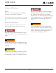
USER GUIDE u-line.com SAFETY • INSTALLATION & INTEGRATION • OPERATING INSTRUCTIONS • MAINTENANCE • SERVICE Safety and Warning ! DANGER NOTICE This unit contains R600a (Isobutane) which is a Please read all instructions before installing, flammable hydrocarbon. It is safe for regular operating, or servicing the appliance. use. Do not use sharp objects to expedite defrosting.
USER GUIDE u-line.com SAFETY • INSTALLATION & INTEGRATION • OPERATING INSTRUCTIONS • MAINTENANCE • SERVICE Disposal and Recycling ! DANGER RISK OF CHILD ENTRAPMENT. Before you throw away your old refrigerator or freezer, take off the doors and leave shelves in place so children may not easily climb inside.
USER GUIDE u-line.com SAFETY • INSTALLATION & INTEGRATION • OPERATING INSTRUCTIONS • MAINTENANCE • SERVICE Environmental Requirements This model is intended for indoor/interior applications only and is not to be used in installations that are open/ exposed to natural elements. This unit is designed to operate between 50°F (10°C) and 100°F (38°C). Higher ambient temperatures may reduce the unit’s ability to reach low temperatures and/or reduce ice production on applicable models.
USER GUIDE u-line.com Electrical ! WARNING SHOCK HAZARD — Electrical Grounding Required. Never attempt to repair or perform maintenance on the unit until the electricity has been disconnected. Never remove the round grounding prong from the plug and never use a two-prong grounding adapter. Altering, cutting or removing power cord, removing power plug, or direct wiring can cause serious injury, fire, loss of property and/or life, and will void the warranty.
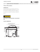
USER GUIDE u-line.com SAFETY • INSTALLATION & INTEGRATION • OPERATING INSTRUCTIONS • MAINTENANCE • SERVICE Cutout Dimensions PREPARE SITE Your U-Line product has been designed for either freestanding or built-in installation. When built-in, your unit does not require additional air space for top, sides, or rear. However, the front grille must NOT be obstructed, and clearance is required for an electrical connection in the rear. ! CAUTION Unit can NOT be installed behind a closed cabinet door.
USER GUIDE u-line.
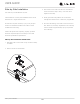
USER GUIDE Side-by-Side Installation u-line.com 3. Place bracket over holes and attach to unit with two screws removed in step 2 using a T-25 Torx driver. Two units may be installed side-by-side. Cutout width for a side-by-side installation is the cutout Tighten screws fully. 4. Gently push units into position. Be careful not to dimension of a single unit times two. No trim kit is required. However, 1/4" (6 mm) of space entangle the electrical cord or water line, if applicable. 5.
USER GUIDE u-line.com SAFETY • INSTALLATION & INTEGRATION • OPERATING INSTRUCTIONS • MAINTENANCE • SERVICE General Installation INSTALLATION 1. Plug in the power/electrical cord. LEVELING INFORMATION 2. Gently push the unit into position. Be careful not to NOTICE entangle the cord. Because these units do not have leveling legs, it is extremely important that they sit on a level 3. Re-check the leveling, from front to back and side to surface. side. Make any necessary adjustments.
USER GUIDE u-line.com SAFETY • INSTALLATION & INTEGRATION • OPERATING INSTRUCTIONS • MAINTENANCE • SERVICE Integrated Panel Dimensions INSERT CUSTOM 1/4'' THICK DOOR PANEL Insert Panel Preparation A custom door panel may be inserted into the door frame. Custom door panels can be flat or raised, as long as the maximum panel thickness where inserted into the door reveal (channel) is no more than 1/4" thick. For raised panels, the depth of the reveal is 1/4" on all four sides.
USER GUIDE u-line.com SAFETY • INSTALLATION & INTEGRATION • OPERATING INSTRUCTIONS • MAINTENANCE • SERVICE Integrated Panel Installation 5. Slide custom door panel insert into 1/4" (6 mm) channel in door front. This model accepts a 1/4" insert panel. INSERT PANEL INSTALLATION NOTICE Install the insert as follows: Use care not to damage magnet, located on door bottom when installing door insert. Do not set door on bottom edge when pushing insert into place. ! CAUTION 6.
USER GUIDE u-line.com SAFETY • INSTALLATION & INTEGRATION • OPERATING INSTRUCTIONS • MAINTENANCE • SERVICE Grille - Plinth Installation 1 3 REMOVING AND INSTALLING GRILLE ! WARNING 4 Disconnect electric power to the unit before 2 removing the grille. When using the unit, the grille (plinth strip/base fascia) must be installed. ! WARNING DO NOT touch the condenser fins. The condenser fins are SHARP and can be easily damaged. Removing the grille 1. Disconnect power to the unit. 2.
USER GUIDE u-line.com SAFETY • INSTALLATION & INTEGRATION • OPERATING INSTRUCTIONS • MAINTENANCE • SERVICE Door Swing All units have a zero clearance for the door to open 90°. U-Line recommends a minimum door clearance of 1/4" (6 mm) to accommodate the handle if the unit is installed next to a wall. 1/4" Min.
USER GUIDE u-line.com SAFETY • INSTALLATION & INTEGRATION • OPERATING INSTRUCTIONS • MAINTENANCE • SERVICE Door Adjustments To reverse the door mounting, perform the following: CHECKING DOOR ALIGNMENT 1. Remove grille (see GRILLE-PLINTH INSTALLATION). The unit’s door is aligned at the factory before shipment. However, its alignment could have been disturbed during 2. Remove top hinge from cabinet (three screws). Hold shipment. door to keep it from falling.
USER GUIDE u-line.com SAFETY • INSTALLATION & INTEGRATION • OPERATING INSTRUCTIONS • MAINTENANCE • SERVICE 9. Remove plastic hole plug from door handle and 6. Install hinge on opposite side at bottom of cabinet. Align hinge outer edge with cabinet before tightening relocate to opposite side. Lift the handle slightly and screws. press on the locking tab, then gently pry the hole plug out of the hole, being careful not scratch the top cap.
USER GUIDE u-line.com SAFETY • INSTALLATION & INTEGRATION • OPERATING INSTRUCTIONS • MAINTENANCE • SERVICE First Use All U-Line controls are preset at the factory. Initial startup requires no adjustments. NOTICE U-Line recommends allowing the unit to run overnight before loading with product. As warm air rises, the temperature inside the unit tends to be slightly warmer at the top and slightly cooler at the bottom.
USER GUIDE u-line.com SAFETY • INSTALLATION & INTEGRATION • OPERATING INSTRUCTIONS • MAINTENANCE • SERVICE Airflow and Product Loading NOTICE The unit requires proper airflow to perform at its highest efficiency. Do not block the front grille, or the unit will not perform as expected. Do not install the unit behind a door. When loading your unit, leave space between the evaporator and product loaded. Anything in direct contact with the evaporator is subject to freezing.
USER GUIDE u-line.com SAFETY • INSTALLATION & INTEGRATION • OPERATING INSTRUCTIONS • MAINTENANCE • SERVICE Interior Shelves REMOVING AND INSTALLING INTERIOR SHELVES For models equipped with glass shelves having shelf supports, remove the shelves as follows: 1. Open door completely. 2. Grasp the shelf edge in the center and slide the shelf from the unit. Insert the shelves as follows: 1.
USER GUIDE u-line.com SAFETY • INSTALLATION & INTEGRATION • OPERATING INSTRUCTIONS • MAINTENANCE • SERVICE Door Shelves REMOVING AND INSTALLING DOOR SHELVES 1 2 To remove the door shelf: 1. Grasp shelf in center, and lift until the shelf notches (1) clear the pins (2). 2. Carefully pull the shelf away from the door. To install the door shelf: 1. Holding the shelf in the center, center the shelf in the door at the desired location, slightly above the pins (2). 2. Lower the shelf onto the pins (2).
USER GUIDE u-line.com SAFETY • INSTALLATION & INTEGRATION • OPERATING INSTRUCTIONS • MAINTENANCE • SERVICE Cleaning If any surface discoloring or rusting appears, clean it EXTERIOR CLEANING and a nonabrasive cloth. Always clean with the grain. Vinyl Clad (Black or White) Always finish with Claire® Stainless Steel Polish and quickly with Bon-Ami® or Barkeepers Friend Cleanser® Cleaner or comparable product to prevent further Clean surfaces with a mild detergent and warm water problems. solution.
USER GUIDE u-line.com SAFETY • INSTALLATION & INTEGRATION • OPERATING INSTRUCTIONS • MAINTENANCE • SERVICE High ambient temperature and excessive humidity can also produce frost. ! CAUTION DO NOT use an ice pick or other sharp instrument to help speed up defrosting. These instruments can puncture the inner lining or damage the cooling unit. DO NOT use any type of heater to defrost. Using a heater to speed up defrosting can cause personal injury and damage to the inner lining.
USER GUIDE u-line.com SAFETY • INSTALLATION & INTEGRATION • OPERATING INSTRUCTIONS • MAINTENANCE • SERVICE Cleaning Condenser INTERVAL - EVERY SIX MONTHS To maintain operational efficiency, keep the front grille free of dust and lint, and clean the condenser when necessary. Depending on environmental conditions, more or less frequent cleaning may be necessary. ! WARNING Disconnect electric power to the unit before cleaning the condenser. ! WARNING DO NOT touch the condenser fins.
USER GUIDE u-line.com SAFETY • INSTALLATION & INTEGRATION • OPERATING INSTRUCTIONS • MAINTENANCE • SERVICE Extended Non-Use VACATION/HOLIDAY, PROLONGED SHUTDOWN The following steps are recommended for periods of extended non-use: 1. Remove all consumable content from the unit. 2. Disconnect the power cord from its outlet/socket and leave it disconnected until the unit is returned to service. 3. If ice is on the evaporator, allow ice to thaw naturally. 4. Clean and dry the interior of the unit.
USER GUIDE u-line.com SAFETY • INSTALLATION & INTEGRATION • OPERATING INSTRUCTIONS • MAINTENANCE • SERVICE Troubleshooting • Evaporator: Refrigerant flowing through an evaporator may sound like boiling liquid. BEFORE CALLING FOR SERVICE If you think your U-Line product is malfunctioning, read • Condenser Fan: Air moving through a condenser may the CONTROL OPERATION section to clearly understand be heard. the function of the control.
USER GUIDE u-line.com SAFETY • INSTALLATION & INTEGRATION • OPERATING INSTRUCTIONS • MAINTENANCE • SERVICE Problem Possible Cause and Remedy Product Is Not Cold Enough. Air temperature does not indicate product temperature. See CHECKING PRODUCT TEMPERATURE below. Adjust the temperate to a cooler set point. Ensure unit is not located in excessive ambient temperatures or in direct sunlight. Ensure the door is closing and sealing properly. Ensure the interior light has not remained on too long.
BLUE 28 BLUE RED BLACK BROWN CONTROL 42341_A WIRING DIAGRAM WHITE SEE COMPRESSOR DIAGRAMS BLACK GROUND: GREEN or GREEN W/ YELLOW WHITE BLACK-HOT (SMOOTH) BLACK-NEUTRAL (RIBBED) 115 VOLT PLUG PLUG RELAY NEUTRAL HOT EMBRACO COMPRESSOR 220-240 VOLT GROUND: GREEN or GREEN W/ YELLOW CAP OVERLOAD USER GUIDE u-line.
USER GUIDE u-line.com SAFETY • INSTALLATION & INTEGRATION • OPERATING INSTRUCTIONS • MAINTENANCE • SERVICE Product Liability Field service technicians are authorized to make an initial assessment in the event of reported damages. If there are any questions about the process involved, the technician should call U-Line for further explanation. While inspecting for defects or installation issues, photos should be taken to document any damages or issues found.
USER GUIDE u-line.com SAFETY • INSTALLATION & INTEGRATION • OPERATING INSTRUCTIONS • MAINTENANCE • SERVICE Warranty Claims warranty status.
Parts U-29RB-00A 1 16 20 14 19 2 3 12 17 10 15 4 7 Item Description U-Line P/N 1 Back panel 80-54505-00 2 Bottle retainer, long 80-54530-00 3 Bottle retainer, short 80-54533-00 4 Compressor electricals only 80-54149-00 5 Compressor w/electricals 80-54150-00 6 Condenser assembly 80-54521-00 7 Condenser fan w/screws 80-54014-00 8 Control assembly 80-54192-00 9 Control knob 80-54382-00 10 Door assembly w/o hinges 80-54514-00 11 Drain pan 80-54217-00 12 Drain trou
USER GUIDE u-line.com SAFETY • INSTALLATION & INTEGRATION • OPERATING INSTRUCTIONS • MAINTENANCE • SERVICE Ordering Replacement Parts If you have a purchasing account, please utilize our service website to order parts. Orders may also be placed by Fax or phone. See our contact information below: www.U-LineService.com (with service login) FAX Number: +1.414.354.5696 Phone Number: +1.800.779.2547 NOTICE Use only genuine U-Line replacement parts.
USER GUIDE u-line.com SAFETY • INSTALLATION & INTEGRATION • OPERATING INSTRUCTIONS • MAINTENANCE • SERVICE R-600A Specifications Gloves and Eye Protection must be used. For R-600a refrigerant service tips and more videos, go to: www.u-line.com/videos. ! WARNING Flammability warnings for a pure-iso-butane refrigerant. R-600a is considered non-toxic, but is flammable when mixed with air. Keep a dry powder type fire extinguisher in the work area.
USER GUIDE u-line.com SAFETY • INSTALLATION & INTEGRATION • OPERATING INSTRUCTIONS • MAINTENANCE • SERVICE R-600A SPECIFICATIONS/LABELING ! WARNING R-600a equipped products are labeled (both the unit and the compressor). Only skilled and well trained service technicians permitted to service R-600a equipped products. R-600a is colorless and odorless. All tools and equipment must be approved for R-600a is considered non-toxic, but is flammable when use with R-600a refrigerant. mixed with air.
USER GUIDE u-line.com SAFETY • INSTALLATION & INTEGRATION • OPERATING INSTRUCTIONS • MAINTENANCE • SERVICE Evacuate/reclaim via the piecing pliers to ensure the When re-brazing, the system must be purged with dry system is empty of R-600a before any system work is nitrogen and at least one access point open to the performed. atmosphere. When re-brazing, proper ventilation is required along with constant monitoring for the presence of R600a refrigerant.
USER GUIDE u-line.com SAFETY • INSTALLATION & INTEGRATION • OPERATING INSTRUCTIONS • MAINTENANCE • SERVICE Proper ventilation during service is required. The low side of the refrigeration system (evaporator, compressor and suction line) must be leak tested with the compressor off (equalized pressure). Never apply a torch to a charged R-600a refrigeration system.
USER GUIDE u-line.
USER GUIDE u-line.com SAFETY • INSTALLATION & INTEGRATION • OPERATING INSTRUCTIONS • MAINTENANCE • SERVICE Compressor Specifications OVERLOAD PROTECTOR STARTING RELAY ! DANGER C S Electrocution can cause death or serious injury. R Burns from hot or cold surfaces can cause serious injury. Take precautions when servicing RELAY COVER CAPACITOR this unit. ULIN_0368_A EMU30HSC Disconnect the power source.
USER GUIDE u-line.com SAFETY • INSTALLATION & INTEGRATION • OPERATING INSTRUCTIONS • MAINTENANCE • SERVICE Troubleshooting - Extended SPECIFIC ERRORS & ISSUES ! CAUTION Never attempt to repair or perform maintenance on the unit until the main electrical power has been disconnected from the unit. TROUBLESHOOTING GUIDE Concern Potential Causes Suggested Remedy Not Cooling Compressor overheating Verify proper air flow through condenser.
USER GUIDE u-line.
USER GUIDE u-line.com SAFETY • INSTALLATION & INTEGRATION • OPERATING INSTRUCTIONS • MAINTENANCE • SERVICE • Condenser Fan: Air moving through a condenser may PRODUCT TEMPERATURE be heard. Causes which affect the internal temperatures of the cabinet include: • Temperature setting. • Automatic Defrost Drain Pan: Water may be heard dripping or running into the drain pan when the unit is in the defrost cycle. • Ambient temperature where installed.
USER GUIDE u-line.
USER GUIDE u-line.com SAFETY • INSTALLATION & INTEGRATION • OPERATING INSTRUCTIONS • MAINTENANCE • SERVICE Harvest-1 Cycle If bin arm is down, power goes through bin arm switch to Temperature control terminals 2 and 3 are open - 2 and 1 the ice maker motor. If bin arm is up, the ice maker will close. not harvest. No power to the compressor or condenser fan. HARVEST-1 CYCLE (Hold Switch In Normal Position) black ON OFF SWITCH black black FAN MOTOR ground brown black COMP.
USER GUIDE u-line.com SAFETY • INSTALLATION & INTEGRATION • OPERATING INSTRUCTIONS • MAINTENANCE • SERVICE Harvest-2 Cycle Ejector blades stall on ice and ice maker motor pulsates Ice maker ejector blades reach approximately 2:00 until mold heater warms and ice releases. position and cam depresses the hold switch. Power goes through the hold switch to the ice maker motor and mold heater.
USER GUIDE u-line.com SAFETY • INSTALLATION & INTEGRATION • OPERATING INSTRUCTIONS • MAINTENANCE • SERVICE Water Fill Cycle Ice maker ejector blades reach approximately 10:00 position and cam depresses the water fill switch. Power to the water valve. Ice maker mold fills. WATER FILL CYCLE black ON OFF SWITCH black black FAN MOTOR ground brown black COMP.
USER GUIDE u-line.com SAFETY • INSTALLATION & INTEGRATION • OPERATING INSTRUCTIONS • MAINTENANCE • SERVICE TEMPERATURE CONTROL SPECIFICATIONS These temperature controls are double throw, single pole controls. The sensing tube is inserted into the ice maker mold and senses mold temperature. After ice is sensed in the mold, the 2-3 contacts open (stopping the compressor) and the 2-1 contacts are closed (starting the ice maker motor).
USER GUIDE u-line.com SAFETY • INSTALLATION & INTEGRATION • OPERATING INSTRUCTIONS • MAINTENANCE • SERVICE LIMIT SWITCH SPECIFICATIONS The function of this switch is to open in the event of an Normally closed Bi-metal switch overheating condition. This bi-metal thermostat is normally closed and does not initiate the ice harvest cycle. The ice harvest cycle is initiated by a double throw, Open temperature: 104°F single pole temperature located remotely from the ice maker assembly.
USER GUIDE u-line.com SAFETY • INSTALLATION & INTEGRATION • OPERATING INSTRUCTIONS • MAINTENANCE • SERVICE FROST FREE REFRIGERATION Defrost Mode Bypass solenoid valve open. Cooling Mode Bypass solenoid closed. Refrigerant flows through bypass system. Evaporator fan operating. Vapor flows from condenser to evaporator without a phase change. Refrigerant flows through capillary tubes. Drain heater on (U-CO29F only). Normal vapor/compression cycle refrigeration.
USER GUIDE u-line.com SAFETY • INSTALLATION & INTEGRATION • OPERATING INSTRUCTIONS • MAINTENANCE • SERVICE Air flow in at evaporator blade Air passes though fin tube evaporator Air flow out at evaporator outlet Condensate drains down past the evaporator, into drain pan, and into condensate pan through drain hose. The drain trough is warmed during defrost by contact with evaporator fins. On U-CO29F model, drain trough is also warmed by drain heater attached to the drain pan.
USER GUIDE u-line.com SAFETY • INSTALLATION & INTEGRATION • OPERATING INSTRUCTIONS • MAINTENANCE • SERVICE Defrost These units are automatic (cycle) defrost unit will defrost itself when the control/sensor is satisfied of internal temperatures. Defrost mode ends when control/sensor asks for cooling.
USER GUIDE u-line.com SAFETY • INSTALLATION & INTEGRATION • OPERATING INSTRUCTIONS • MAINTENANCE • SERVICE U-Line Corporation (U-Line) Limited Warranty One Year Limited Warranty For one year from the date of original purchase, this U-Line product warranty covers all parts and labor to repair or replace any part of the product that proves to be defective in materials or workmanship.