
User Guide & Service Manual

USER GUIDE
Troubleshooting - Extended 4
u-line.com
SAFETY • INSTALLATION & INTEGRATION • OPERATING INSTRUCTIONS • MAINTENANCE • SERVICE
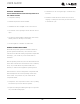
REFRIGERATION SYSTEM DIAGNOSIS GUIDE
ICE MAKER OPERATING CYCLES
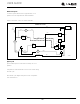
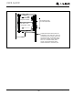
Freeze Cycle
Temperature control terminals 2 and 3 are closed.
Power to the compressor.
Power to the condenser fan.
System
Condition
Suction
Pressure
Suction
Line
Compressor
Discharge
Condenser Capillary
Tube
Evaporator Wattage
Normal Normal Slightly below
room
temperature
Very hot Very hot Warm Cold Normal
Overcharge Higher than
normal
Very cold -
may frost
heavily
Slightly warm
to hot
Hot to warm Cool Cold Higher than
normal
Undercharge Lower than
normal
Warm -
near room
temperature
Hot Warm Warm Extremely cold
near inlet -
outlet below
room
temperature
Lower than
normal
Partial
Restriction
Somewhat
lower than
normal -
in vacuum
Warm -
near room
temperature
Very hot Top passes warm
lower passes
cool (near room
temperature due
to liquid
Room
temperature
(cool) or colder
Extremely cold
near inlet -
outlet below
room
temperature
backing up
Lower than
normal
Complete
Restriction
In deep
vacuum
Room
temperature
(cool)
Room
temperature
(cool)
Room
temperature
(cool)
Room
temperature
(cool)
No refrigeration Lower than
normal
No Gas 0 PSIG to 25" Room
temperature
(cool)
Cool to hot Room
temperature
(cool)
Room
temperature
(cool)
No refrigeration Lower than
normal
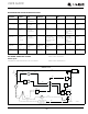
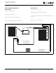
FREEZE CYCLE
SWITCH
LIMIT
orange
black
black
black
MOTOR
MAKER
ICE
MOLD HEATER
WATER
SWITCH
FILL
C
NC
MOTOR
FAN
LOAD
OVER
black
RELAY
START
COMP.
SWITCH
OFF
ON
black
black
blue
black
CONTROL
TEMP.
NC
black
orange
3
yellow
2
orange
SWITCH
BIN
red
NO
1
C
NO
brown
black
white
C
SWITCH
HOLD
VALVE
WATER
ground
UL183-4
42