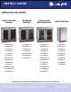
INSTALL GUIDE ® MODULAR 3000 SERIES WINE CAPTAIN® MODELS BEVERAGE CENTERS GLASS DOOR REFRIGERATORS REFRIGERATORS U-3018WCOL-00 U-3024BEVOL-00 U-3018RGLOL-00 U-3018RFOL-00 U-3018WCOL-01 U-3024BEVOL-01 U-3018RGLOL-01 U-3018RFOL-01 U-3018WCS-00 U-3024BEVS-00 U-3018RGLS-00 U-3018RFS-00 U-3018WCS-01 U-3024BEVS-01 U-3018RGLS-01 U-3018RFS-01 U-3018WCS-13 U-3036BVWCOL-00 U-3018RGLS-13 U-3024RFOL-00 U-3018WCS-15 U-3036BVWCS-00 U-3018RGLS-15 U-3024RFOL-01 U-3024WCOL-00 U-3036BVWCS-13
1 Table of Contents Safety Precautions Safety Alert Definitions ........................................................................................................................................ 1 General Precautions.............................................................................................................................................. 1 Inspect & Plan Product Registration .............................................................................................................
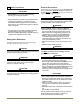
General Precautions 2 Safety Precautions IMPORTANT • PLEASE READ all instructions before installing, operating, or servicing the appliance. • Proper installation procedures must be followed when completing an installation or relocation of a unit. Consult the installation guide before any installation begins. U-Line contact information appears on the rear cover of this guide. • This unit requires connection to a dedicated 15 Amp grounded (three-prong), polarized receptacle.
Exterior Cleaning 3 Inspect & Plan IMPORTANT Stainless door panels, handles and frames can discolor when exposed to chlorine gas, pool chemicals, salt water or cleaners with bleach. Product Registration You have received a carton containing your 3000 series unit with a package inside containing a Use and Care Guide and a Product Registration Card. Please complete and mail the Product Registration Card or register online at www.U-LineService.com.
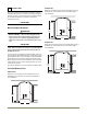
3024 Series 4 Prepare Site Your U-Line product has been designed exclusively for a built-in installation. When built-in, your unit does not require additional air space for top, sides, or rear. However, the front grille must NOT be obstructed and clearance is required for an electrical connection in the rear. Follow the cut-out drawing. The 23-7/8" width allows for ease in installation and removal of the unit. 24" is the cabinet depth in most installations.
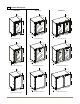
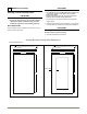
3018, 3024 & 3036 Series 5 Product Dimensions 3024 Series 3018 Series 3036 Series 22-11/16" 22-11/16" 33-11/16" To 34-11/16" 33-11/16" To 34-11/16" 4-3/4" To 5-3/4" 17-3/4" 22-11/16" 4-3/4" To 5-3/4" 33-11/16" To 34-11/16" 23-5/8" 35-7/16" 4-3/4" To 5-3/4" Glass & Solid Overlay Glass & Solid Overlay Glass & Solid Overlay 23-7/16" 23-7/16" 23-7/16" 33-11/16" To 34-11/16" 33-11/16" To 34-11/16" 33-11/16" To 34-11/16" 3-5/8" To 4-5/8" 3-5/8" To 4-5/8" 23-5/8" 35-7/16" 3-5/8" To 4-5/8
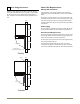
Other Site Requirements 6 Door Swing Dimensions Side-By-Side Installation Units have a zero clearance for the door to open 90°. Overlay models will need additional space for any knobs or pulls installed on the overlay panel / frame. Stainless Steel models require 2" door clearance to accommodate the handle if installed next to a wall. Wall Cut-out width for a side-by-side installation is the total of the widths listed under Cut-Out Dimensions in each unit’s Installation Guide. No trim kit is required.
3. Gently pull bottom of wrap away from door. 7 3000 Series Doors Door Alignment and Adjustment 4. The Wrap hinges on top of the door. Carefully pull wrap away and then up. See below. Align and adjust the door if it is not level, or is not sealing properly. If the door is not sealed the unit may not cool properly, or excessive frost or condensation may form in the interior.
8 3000 Series Overlays IMPORTANT Overlay / Frame Overlay Panel IMPORTANT • The door panel must not weigh more than 20lbs. • It is important to ensure that all drilled holes are drilled to the correct depth in order to avoid splits in the wood when hardware is installed. Appliance will need up to 34 1/2" to the under side of the counter to leave room for leveling adjustments. • Due to differences in surrounding cabinetry the panel may not perfectly align with door.
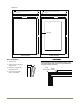
3024 Series BACK SURFACE MUST HAVE AMPLE FLAT SURFACE TO MOUNT OVERLAY PANEL FLAT AND WITHOUT INTERFERENCE 3/4" MIN BACK SURFACE MUST HAVE AMPLE FLAT SURFACE TO MOUNT OVERLAY FRAME FLAT AND WITHOUT INTERFERENCE 23-1/2" 3/4" MIN 23-1/2" 2 3/4" Min 30" 30" Solid Overlay Frame Overlay Panel Installation 1. Fully open door, 2. Starting at corner, pull gasket away from door. 3. Continue to pull gasket free from gasket channel.
5. The frame should be aligned with the outside edge (opposite the hinge) and high enough to align with the highest point in the door. 10. Be sure the screws force their way past the opening on the gasket channel and sit flush against the bottom of the channel. Align Top Of Panel With Highest Point Of Door Align Frame Against Door Edge First Due to differences in floor construction or surrounding cabinetry, the frame may not sit flush with the top of the door. Door Overlay Panel 11.
1-15/32" 1-15/32" U-Line Door Panel Installation Guide 3036 Models 33-9/32" 35-7/32" 3024 Models 20-3/8" 23-9/16" 3018 Models 15-19/32" 17-17/32" 1" 1" A Dimension A may vary from a minimum of 3-1/4" to a maximum 4-1/4" depending on toe kick height. Measure toe kick height and cut overlay to same dimension.
9 3000 Series Anti-Tip Bracket Anti-Tip Brackets Installation 3036 Side Mount Side mount configurations work well if you have a granite counter top or do not wish to mount the brackets to the underside of your counter top. 1. Align each bracket to the side mounting holes on your model as shown below. WARNING The Anti-tip bracket must be installed to prevent the unit from tipping when doors are fully opened, or excess weight is placed on the front of the unit.
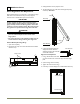
3018/3024 Top Mount 3018/3024 Side Mount Left View Of Cabinet Right View Of Cabinet Top mount configurations work well with fully secured wood or laminate counter tops. 1. Align the brackets on top of your unit as shown below. Both brackets must be used to ensure a secure mount. 2. Using 4 of the supplied 10 #8 5/8" screws, install 2 screws into each plate using a #2 Phillips head screwdriver. 3. Completely slide the unit into its position in the cabinet. Be certain unit height is properly adjusted.
Installation 10 10 Level & Install 1. Plug in the powercord. Leveling Information It is recommended that the unit is level once installed. 1. Use a level to check the levelness of the unit from front to back and from side to side. Level should be placed along top edge and side edge as shown. 2. Gently push the unit into position. Be careful to not entangle the electrical cord. 3. Re-check the leveling, from front to back and side to side. Make any necessary adjustments.
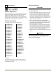
INSTALLATION GUIDE ® SERVICE INFORMATION If you have a problem with this appliance, your use and care guide has troubleshooting information to help you quickly identify common problems and provide information on possible cause and remedy. Answers to Customers Frequently Asked Questions are available at www.u-line.com/customer/faq.cfm. You may contact U-Line directly: GENERAL INQUIRIES: SERVICE ASSISTANCE: U-Line Corporation P.O. Box 245040 Milwaukee, Wisconsin 53224-9540 U.S.A.