
User Guide & Service Manual

USER GUIDE
Control Operation - Service 2
u-line.com
SAFETY • INSTALLATION & INTEGRATION • OPERATING INSTRUCTIONS • MAINTENANCE • SERVICE
SERVICE MENU
In addition to a feature rich customer menu, the 3000
series also offers a service menu with the ability to fine
tune and monitor unit operation.
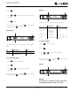
To initiate the Service menu hold both and for 5
seconds.
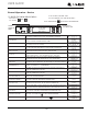
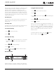
Actual Temps
The Actual Temp option in the service menu will display
raw thermistor readings without calculating offsets.
1. Press to select “Actual Temps”.
2. Press .
3. Use and to scroll through available thermistor
readings.
To exit the Actual Temps menu press to select “Return
to Menu” and press to confirm.
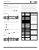
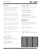
All Errors
The All Errors option keeps record of any system errors.
When an error occurs it is recorded to all errors. The
number next to the error indicates the number of recorded
instances. Errors in the log may not be currently active.
The error log memory is non volatile and is persistent
should power be lost and restored to the unit. See below
for a list of logged errors and their respective descriptions.
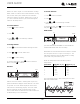
Up
Select
Down
RETURN TO MENU
ACTUAL TEMPS
ZONE = 2°C
EVAP = °C
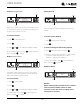
Up
Error ID
Number
Of Occurrences Select
Down
RETURN TO MENU
ALL ERRORS
NO COMM 0
ZONE T OPEN 0
ID Descrip tion Solution
No Comm
Unit lost communication to the
display
Check connection to Display board and
Main board. Check integrity of wires. If
unit not operational, replace wire, if
functioning properly, then software re-set
and no ad
j
ustments are needed.
L Zone T Open
Left Zone thermistor circuit
open
R Zone T Open
Right Zone thermistor circuit
o
p
en
L Evap T Open
Left Evaporator thermistor
circuit o
p
en
R Evap T Open
Right Evaporator thermistor
circuit o
p
en
Amb Thrm Open Ambient thermistor circuit open
L Zone T Short
Left Zone thermistor circuit
short
R Zone T Short
Right Zone thermistor circuit
short
L Evap T Short
Left Evaporator thermistor
circuit short
R Evap T Short
Right Evaporator thermistor
circuit short
Amb Thrm Short Ambient thermistor circuit
short
L Temp Hi 6H+
Left Zone temperature +10°F
(+5°C) over set point for over 6
hours
R Temp Hi 6H+
R Zone temperature +10°F
(+5°C) over set point for over 6
hours
L Temp Hi 12H+
Left Zone temperature +10°F
(+5°C) over set point for over
12 hours
R Temp Hi 12H+
R Zone temperature +10°F
(+5°C) over set point for over
12 hours
L Temp Lo 6H+
Left Zone temperature -10°F
(-5°C) over set point for over 6
hours
R Temp Lo 6H+
R Zone temperature -10°F
(-5°C) over set point for over 6
hours
L Temp Lo 12H+
Left Zone temperature -10°F
(-5°C) over set point for over
12 hours
R Temp Lo 12H+
R Zone temperature -10°F
(-5°C) over set point for over
12 hours
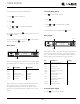
L Door Open 5M
Left door switch open for more
than 5 minutes.
R Door Open 5M
Right door switch open for
more than 5 minutes.
Check thermistor connection to harness for
moisture or corrosion. Also check
connection where thermistor harness
attaches to main board. If connections are
valid replace the thermistor.
NOTE: DWR/ZWC models, L indicates TOP
zone, R indicates BOTTOM zone.
Is condenser coil clean? Is condenser fan
operating? Check zone thermistor for
correct resistance. Verify thermistor
connections are clean and intact. Check
zone valve operation. Sealed system issue?
NOTE: DWR/ZWC models, L indicates TOP
zone, R indicates BOTTOM zone.
Verify thermistor connections are clean and
dry. Verify thermistor resistance. Verify
correct operation of zone valve.
NOTE: DWR/ZWC models, L indicates TOP
zone, R indicates BOTTOM zone.
Check door switch magnet reed switch
alignment when door is in closed position.
Check reed switch connection at the
harness and the main board.
NOTE: DWR models, L indicates TOP
drawer, R indicates BOTTOM drawer.
NOTE: ZWC models indicate L Door for the
only door present.
53