USER GUIDE & SERVICE MANUAL ADA Series ● UACP115 ● 15” Clear Ice Machine with Pump
USER GUIDE & SERVICE MANUAL u-line.
USER GUIDE u-line.com WELCOME TO U-LINE Congratulations on your U-Line purchase. Your product comes from a company with over five decades of premium modular ice making, refrigeration, and wine preservation experience. U-Line creates products focused on functionality, style, and inspired innovations — paying close attention to even the smallest details. Applications include residential, outdoor, ADA height compliant, marine, and commercial.
USER GUIDE u-line.com Safety and Warning ! DANGER NOTICE This unit contains R600a (Isobutane) which is a Please read all instructions before installing, flammable hydrocarbon. It is safe for regular operating, or servicing the appliance. use. Do not use sharp objects to expedite Use this appliance for its intended purpose only and follow these general precautions with those listed throughout this guide: defrosting.
USER GUIDE u-line.com Disposal and Recycling ! DANGER RISK OF CHILD ENTRAPMENT. Before you throw away your old refrigerator or freezer, take off the doors and leave shelves in place so children may not easily climb inside. If the unit is being removed from service for disposal, check and obey all federal, state, and local regulations regarding the disposal and recycling of refrigeration appliances, and follow these steps completely: 1. Remove all consumable contents from the unit. 2.
USER GUIDE u-line.com Environmental Requirements This model is intended for indoor/interior applications only and is not to be used in installations that are open/ exposed to natural elements. This unit is designed to operate between 50°F (10°C) and 100°F (38°C). Higher ambient temperatures may reduce the unit’s ability to reach low temperatures and/or reduce ice production on applicable models. For best performance, keep the unit out of direct sunlight and away from heat generating equipment.
USER GUIDE u-line.com Electrical ! WARNING SHOCK HAZARD — Electrical Grounding Required. Never attempt to repair or perform maintenance on the unit until the electricity has been disconnected. Never remove the round grounding prong from the plug and never use a two-prong grounding adapter. Altering, cutting or removing power cord, removing power plug, or direct wiring can cause serious injury, fire, loss of property and/or life, and will void the warranty.
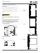
USER GUIDE u-line.com 14 7⁄8” (378 mm) Cutout & Product Dimensions PREPARE SITE Your U-Line product has been designed for either freestanding or built-in installation. When built-in, your unit does not require additional air space for top, sides, or rear. However, the front grille must NOT be obstructed, FRONT and clearance is required for an electrical connection in 34 1⁄4” to 35 1⁄4” (870 mm to 895 mm) 28” (711 mm) 28” (711 mm) the rear.
USER GUIDE u-line.com Side-by-Side Installation Hinge-by-Hinge Installation (Mullion) When installing two units hinge-by-hinge, 13/16” (22 mm) OTHER SITE REQUIREMENTS is required for integrated models. Additional space may be needed for any knobs, pulls or handles installed. Side-by-Side Installation 13⁄16” (22 mm) Units must operate from separate, properly grounded electrical receptacles placed according to each unit’s electrical specifications requirements.
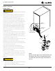
USER GUIDE u-line.com Water Hookup WATER SUPPLY ! CAUTION Observe and follow all local building codes when installing this appliance. This ice machine must be connected to a potable cold water supply line. delivering water pressure between a minimum of 20 psi and a maximum of 120 psi. Use 1⁄4” copper tubing for your water supply which is available at any local hardware or plumbing supply store. Route the 1⁄4” copper tubing to suit your installation being Water Supply Line sure not to kink the tubing.
USER GUIDE u-line.com Drain Air Gap (Optional Hook-Up) DRAIN CONNECTION ! CAUTION The floor drain must be large enough to Waste accommodate drainage from all attached drains.
USER GUIDE u-line.com General Installation INSTALLATION LEVELING INFORMATION 1. Use a level to 1. Plug in the power/electrical cord. 2. Gently push the unit into position. Be careful not to entangle the cord or water and drain lines, if confirm the unit is applicable. level. Level should 3. be placed along top Re-check the leveling, from front to back and side to edge and side edge side. Make any necessary adjustments. The unit’s top as shown.
USER GUIDE u-line.com Grille Installation REMOVING AND INSTALLING GRILLE ! WARNING Disconnect electric power to the unit before removing the grille. When using the unit, the grille must be installed. ! WARNING Do NOT touch the condenser fins. The condenser fins are SHARP and can be easily damaged. Removing the grille 1. Disconnect power to the unit. 2. Remove the two screws. 3. Remove grille from unit. Installing the grille 1.
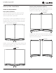
USER GUIDE USER GUIDE u-line.com u-line.com SAFETY • INSTALLATION & INTEGRATION • OPERATING INSTRUCTIONS • MAINTENANCE • SERVICE Door Swing Wall Wall 1/4" Min. (6 mm) 90 Door Swing 2-1/8" Min. (54 mm) 90 Door Swing Units have a zero clearance for the door to open 90°, when installed adjacent to cabinets. Stainless Steel and black and white models require 2-1/8" (54 mm) door clearance to accommodate the handle if installed next to a wall.
USER GUIDE u-line.com Door Adjustments 2. With a Phillips screwdriver, remove the bushing screw and hing pin from the bottom hinge. REVERSING THE DOOR Cam Closer Location of the unit may make it desirable to mount the door on the opposite side of the cabinet. The hinge hardware will be removed and reinstalled on the opposite side of the cabinet.
USER GUIDE 7. u-line.com Using a Phillips screwdriver, remove the toe kick from the door and attach it to the opposite side. Toe Kick Reversal 8. Reinstall the door.
USER GUIDE u-line.com First Use Initial startup requires no adjustments. See CONTROL OPERATION section for more details. NOTICE U-Line recommends discarding the ice produced during the first two to three hours of operation to avoid possible dirt or scale that may dislodge from the water line. When plugged in, the unit will begin operating under the factory default settings. If the unit was turned off during installation, simply press and the unit will immediately switch on.
USER GUIDE u-line.com Control Operation Electronic Control Control Function Guide Function Command Notes ON/OFF Press and release. Unit will immediately turn ON or OFF. Enable Sabbath Mode Press and hold for 5 seconds and release. The oF / oC symbol will flash briefly after 5 seconds. Interior light and display will go dark and remain so until user resets mode - unit continues to operate. Disable Sabbath Mode Press and release. Display and interior light return to normal operation.
USER GUIDE u-line.com Evaporator ICE Front Panel Your ice machine is unique in how it forms ice with Grid Cutter fractional freezing to form a slab of ice that is clear and has less dissolved solids than the water from which it is produced. This is accomplished by running water over the cold evaporator plate which gradually freezes the water to Ice Deflector produce the ice slab. Pure water freezes first, leaving the dissolved solids in the residual reservoir water.
USER GUIDE u-line.com Cleaning Condenser INTERVAL - EVERY SIX MONTHS To maintain operational efficiency, keep the front grille free of dust and lint, and clean the condenser when necessary. Depending on environmental conditions, more or less frequent cleaning may be necessary. ! WARNING Disconnect electric power to the unit before cleaning the condenser. ! WARNING DO NOT touch the condenser fins. The condenser fins are SHARP and can be easily damaged.
USER GUIDE u-line.com Extended Non-Use VACATION/HOLIDAY, PROLONGED SHUTDOWN The following steps are recommended for periods of extended non-use: 1. Remove all consumable content from the unit. 2. Disconnect the power cord from its outlet/socket and leave it disconnected until the unit is returned to service. 3. If any ice is visible inside the unit, allow ice to thaw naturally. 4. Clean and dry the interior of the unit. Ensure all water has been removed from the unit. 5. Clean the system.
USER GUIDE u-line.com Troubleshooting • Evaporator: Refrigerant flowing through an evaporator may sound like boiling liquid. BEFORE CALLING FOR SERVICE • Condenser Fan: Air moving through a condenser may be heard. • Running Water: As your unit continues to produce ice you will hear water flowing into the collection chambers and running through the evaporator. If you think your U-Line product is malfunctioning, read the CONTROL OPERATION section to clearly understand the function of the control.
USER GUIDE u-line.com Product Liability Field service technicians are authorized to make an initial assessment in the event of reported damages. If there are any questions about the process involved, the technician should call U-Line for further explanation. While inspecting for defects or installation issues, photos should be taken to document any damages or issues found.
USER GUIDE Warranty Claims The following information defines the parameters for filing a warranty claim: Units must be registered prior to warranty submittal. Customers may register at www.U-Line.com. A proof of purchase is required. We also accept the following information to update warranty: • Valid serial number needed • Valid model number needed • Claims must be submitted online at www.U-LineService.com • u-line.
Service Parts List USER GUIDE u-line.com u-line.
USER GUIDE u-line.com Ordering Replacement Parts Parts may be ordered online at www.U-Line.com See our contact information below: www.U-LineService.com (with service login) Phone Number: +1.414.354.0300 NOTICE Use only genuine U-Line replacement parts. The use of non-U-Line parts can reduce speed of ice production, cause water to overflow from ice maker mold, damage the unit, and void the warranty. Warranty parts will be shipped at no charge after U-Line confirms warranty status.
USER USER GUIDE GUIDE u-line.com u-line.com SAFETY • INSTALLATION & INTEGRATION • OPERATING INSTRUCTIONS • MAINTENANCE • SERVICE R-600A Specifications Gloves and Eye Protection must be used. For R-600a refrigerant service tips and more videos, go to: www.u-line.com/videos. ! WARNING Flammability warnings for a pure-iso-butane refrigerant. R-600a is considered non-toxic, but is flammable when mixed with air. Keep a dry powder type fire extinguisher in the work area.
USER USER GUIDE GUIDE u-line.com u-line.com SAFETY • INSTALLATION & INTEGRATION • OPERATING INSTRUCTIONS • MAINTENANCE • SERVICE ! WARNING Only skilled and well trained service technicians permitted to service R-600a equipped products. R-600A SPECIFICATIONS/LABELING R-600a equipped products are labeled (both the unit and the compressor). R-600a is colorless and odorless. All tools and equipment must be approved for use with R-600a refrigerant.
USER GUIDE GUIDE USER u-line.com u-line.com SAFETY • INSTALLATION & INTEGRATION • OPERATING INSTRUCTIONS • MAINTENANCE • SERVICE Evacuate/reclaim via the piecing pliers to ensure the When re-brazing, the system must be purged with dry system is empty of R-600a before any system work is nitrogen and at least one access point open to the performed. atmosphere. When re-brazing, proper ventilation is required along with constant monitoring for the presence of R600a refrigerant.
USER GUIDE GUIDE USER u-line.com u-line.com SAFETY • INSTALLATION & INTEGRATION • OPERATING INSTRUCTIONS • MAINTENANCE • SERVICE The low side of the refrigeration system (evaporator, Proper ventilation during service is required. compressor and suction line) must be leak tested with the compressor off (equalized pressure). Never apply a torch to a charged R-600a refrigeration system. RECHARGING No air is ever to be allowed inside the refrigeration system (R-600a refrigerant or dry nitrogen only).
USER GUIDE u-line.
USER GUIDE Compressor Specifications u-line.
USER GUIDE u-line.com Control Operation-Service CONTROL FUNCTION GUIDE UI BUTTON LAYOUT 1 2 3 4 5 6 FUNCTION COMMAND ON/OFF Press Clean Mode See “Cleaning” section Sabboth Mode See “Sabboth Mode” section DISPLAY/OPTIONS and release Unit will immediately turn ON or OFF 1. Hidden Button Showroom Mode • Access Service Menu This mode is designed to show units in a display • No LED directly above. All LED’s turn on with button environment.
USER GUIDE Thermistor u-line.com Thermistor Resistance Data Thermistors are used for various temperature readings. Thermistors provide reliable temperature readings using a resistance which varies based on surrounding temperatures. If a faulty thermistor is suspected, it may be tested using an accurate ohmmeter. Thermistor connections must be kept clean.
U-Line Corporation (U-Line) Limited Warranty One Year Limited Warranty For one year from the date of original purchase, this warranty covers all parts and labor to repair or replace any part of the product that proves to be defective in materials or workmanship. For products installed and used for normal residential use, material cosmetic defects are included in this warranty, with coverage limited to 60 days from the date of original purchase.