USER GUIDE SAFETY • INSTALLATION & INTEGRATION • OPERATING INSTRUCTIONS • MAINTENANCE • SERVICE RIGHT PRODUCT. RIGHT PLACE. RIGHT TEMPERATURE. SINCE 1962.
USER GUIDE & SERVICE MANUAL u-line.
USER GUIDE USER GUIDE u-line.com u-line.com WELCOME TO U-LINE WELCOME TO U-LINE Congratulations on your U-Line purchase. Your product comes from a company with over five decades of premium modular Congratulations on your U-Line purchase. Your product comes from a company with over five decades of premium modular ice ice making, refrigeration, and wine preservation experience. U-Line continues to be the American leader, delivering versatility making, refrigeration, and wine preservation experience.
USER GUIDE u-line.com Safety and Warning This appliance is not intended for use by persons NOTICE mental capabilities, or lack of experience or knowledge, Please read all instructions before installing, operating, or servicing the appliance.
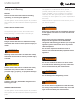
USER GUIDE u-line.com ! WARNING DO NOT use medical devices or other means to accelerate the defrosting process other than those recommended by the manufacturer. DO NOT use an ice pick or other sharp instrument to help speed up defrosting. These instruments can puncture the inner lining or damage the cooling unit. DO NOT use any type of heater to defrost. Using a heater to speed up defrosting can cause personal injury and damage to the inner lining. NOTICE Do not lift unit by door handle.
USER GUIDE u-line.com SAFETY • INSTALLATION & INTEGRATION • OPERATING INSTRUCTIONS • MAINTENANCE • SERVICE Disposal and Recycling ! DANGER RISK OF CHILD ENTRAPMENT. Before you throw away your old refrigerator or freezer, take off the doors and leave shelves in place so children may not easily climb inside.
USER GUIDE u-line.com Environmental Requirements This model is intended for indoor/interior applications only and is not to be used in installations that are open/exposed to natural elements. This unit is designed to operate between 50°F (10°C) and 90°F (32°C). Higher ambient temperatures may reduce the unit’s ability to reach low temperatures and/or reduce ice production on applicable models. For best performance, keep the unit out of direct sunlight and away from heat generating equipment.
USER GUIDE Electrical ! WARNING SHOCK HAZARD - Electrical Grounding Required. Never attempt to repair or perform maintenance u-line.com NOTICE Electrical installation must observe all state and local codes. This unit requires connection to a grounded (three-prong), polarized receptacle that has been placed by a qualified electrician. on the unit until the electricity has been The unit requires a grounded and polarized 220-240 VAC, disconnected. 50 Hz, 8A power supply (normal household current).
USER GUIDE Side-by-Side Installation u-line.com 3. Place bracket over holes and attach to unit with two screws removed in step 2 using a T-25 Torx driver. Two units may be installed side-by-side. Cutout width for a side-by-side installation is the cutout Tighten screws fully. 4. Gently push units into position. Be careful not to dimension of a single unit times two. No trim kit is required. However, 1/4" (6 mm) of space entangle the electrical cord or water line, if applicable. 5.
USER GUIDE u-line.com SAFETY • INSTALLATION & INTEGRATION • OPERATING INSTRUCTIONS • MAINTENANCE • SERVICE Water Hookup ! CAUTION PREPARE PLUMBING Do not use any plastic water supply line. The line The water valve uses a standard 1/4" (6.35 mm) is under pressure at all times. Plastic may crack compression fitting. U-Line recommends using accessory or rupture with age and cause damage to your water hook up kit – part # 80-54674-00. The kit includes a home.
USER GUIDE u-line.com SAFETY • INSTALLATION & INTEGRATION • OPERATING INSTRUCTIONS • MAINTENANCE • SERVICE 3. Locate water valve inlet. 9. Install retaining clip. 4. Break away filler feature in bushing with flat screwdriver. Remove ZLWK ɠDW screwdriver 5. Thread water line through back panel hole (with bushing). 6. Locate water valve inlet and connect to valve. 7. Turn on water supply and check for leaks. 8. Reinstall back panel.
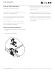
USER GUIDE u-line.com SAFETY • INSTALLATION & INTEGRATION • OPERATING INSTRUCTIONS • MAINTENANCE • SERVICE Anti-Tip Bracket 1. Slide unit out so screws on top of unit are easily accessible. 2. Remove the two screws from the opposite side of the hinge assembly using a T-25 Torx driver (see below). NOTE: 1224 models shown with four screw. 1215 models only have three screws, but same screws are used in both applications. 3.
USER GUIDE u-line.com SAFETY • INSTALLATION & INTEGRATION • OPERATING INSTRUCTIONS • MAINTENANCE • SERVICE General Installation INSTALLATION 1. Plug in the power/electrical cord. LEVELING INFORMATION 1. Use a level to 2. Gently push the unit into position. Be careful not to confirm the unit is kink the water supply line or entangle the cord. level. Level should be placed along top 3. Re-check the leveling, from front to back and side to edge and side edge side. Make any necessary adjustments.
USER GUIDE USER GUIDE u-line.com u-line.com SAFETY • INSTALLATION & INTEGRATION • OPERATING INSTRUCTIONS • MAINTENANCE • SERVICE Integrated Panel Dimensions Integrated Panel Dimensions INTEGRATED PANEL BACK SURFACE MUST HAVE AMPLE FLAT SURFACE TO MOUNT OVERLAY PANEL FLAT AND WITHOUT 3/4" INTERFERENCE (20 mm) NOTICE 14-3/4" (375 mm) Due to differences in surrounding cabinetry the panel may not perfectly align with door.
QUICK START GUIDE USER GUIDE (Amended) u-line.com u-line.com SAFETY • INSTALLATION & INTEGRATION • OPERATING INSTRUCTIONS • MAINTENANCE • SERVICE Integrated Panel Installation NOTICE Due to differences in floor construction or 1. Fully open door/drawer. surrounding cabinetry, the panel may not sit flush with the top of the door/drawer. 2. Starting at corner, pull gasket away from door/ drawer. Panel Door 3. Continue to pull gasket free from gasket channel. 4. Upon removal, lay gasket 9.
USER GUIDE USER GUIDE u-line.com u-line.com SAFETY • INSTALLATION & INTEGRATION • OPERATING INSTRUCTIONS • MAINTENANCE • SERVICE 12.Using a Phillips screwdriver, place one screw into each of the 6 pilot holes and screw down. Do not overtighten screws. 13.Be sure the screws force their way past the opening on the gasket channel and sit flush against the bottom of the channel. Integrated Panel Integrated Panel 14.Remove clamps from door/drawer.
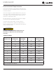
USER GUIDE u-line.com SAFETY • INSTALLATION & INTEGRATION • OPERATING INSTRUCTIONS • MAINTENANCE • SERVICE Door Swing Wall Wall 1/4" Min. (6 mm) 90 Door Swing 2-1/8" Min. (54 mm) 90 Door Swing Units have a zero clearance for the door to open 90°, when installed adjacent to cabinets. Stainless Steel and black and white models require 2-1/8" (54 mm) door clearance to accommodate the handle if installed next to a wall. Integrated models require 1/4" (6 mm) clearance if installed next to a wall.
USER GUIDE u-line.com SAFETY • INSTALLATION & INTEGRATION • OPERATING INSTRUCTIONS • MAINTENANCE • SERVICE Door Stop 3. On 24" models, a second pin is included for the bottom hinge. Repeat steps above for second hinge. Your U-Line unit was shipped to you with the optional 90° pin(s). (Models that are 15" wide include 1 pin. Models NOTE: Threaded pin will be inserted from the bottom. that are 24" wide include 2 pins.) The unit’s door will open freely without a fixed opening angle limitation.
USER GUIDE u-line.com SAFETY • INSTALLATION & INTEGRATION • OPERATING INSTRUCTIONS • MAINTENANCE • SERVICE Door Adjustments DOOR ALIGNMENT AND ADJUSTMENT Align and adjust the door if it is not level or is not sealing properly. If the door is not sealed, the unit may not cool properly, or excessive frost may form in the interior. NOTICE Properly aligned, the door’s gasket should be firmly in contact with the cabinet all the way around the door (no gaps).
USER GUIDE u-line.com SAFETY • INSTALLATION & INTEGRATION • OPERATING INSTRUCTIONS • MAINTENANCE • SERVICE Remove bottom hinge: Prepare door for reinstallation: 1. Remove bottom hinge from cabinet. 1. Rotate door 180° to reverse. 2. Remove gasket center strip and apply in-line with new opening (approximately 2" lower). Install top hinge and door: 1. Use alternate hinge supplied with unit and reinstall the screws. 2. Remove corresponding screws on opposite side of cabinet.
USER GUIDE u-line.com SAFETY • INSTALLATION & INTEGRATION • OPERATING INSTRUCTIONS • MAINTENANCE • SERVICE First Use All U-Line controls are preset at the factory. Initial startup requires no adjustments. NOTICE U-Line recommends discarding the ice produced during the first two to three hours of operation to avoid possible dirt or scale that may dislodge from the water line. ON OFF To turn the unit on or off: Press the rocker switch located inside the door on the front panel, or behind the grille.
USER GUIDE u-line.com SAFETY • INSTALLATION & INTEGRATION • OPERATING INSTRUCTIONS • MAINTENANCE • SERVICE Ice ! CAUTION ICE MAKER OPERATION When the ice bucket is full, the ice making mechanism will NEVER use an ice pick, knife or other sharp shut off. However, the refrigeration system will continue instrument to separate cubes. Shake the ice to cool and maintain the ice supply. bucket instead.
USER GUIDE u-line.com SAFETY • INSTALLATION & INTEGRATION • OPERATING INSTRUCTIONS • MAINTENANCE • SERVICE 3. Turn the adjusting screw toward the minus (-) sign ICE MAKER ADJUSTMENT (clockwise) for smaller cubes or toward the plus (+) Ice Cube Thickness Adjustment sign (counterclockwise) for larger cubes. Interval - As Required On ice maker equipped models, adjust the cube size by 4. Install the ice maker assembly cover.
USER GUIDE u-line.com SAFETY • INSTALLATION & INTEGRATION • OPERATING INSTRUCTIONS • MAINTENANCE • SERVICE Airflow and Product Loading NOTICE The unit requires proper airflow to perform at its highest efficiency. Do not block the front grille at any time, or the unit will not perform as expected. Do not install the unit behind a door.
USER GUIDE u-line.com SAFETY • INSTALLATION & INTEGRATION • OPERATING INSTRUCTIONS • MAINTENANCE • SERVICE Cleaning If any surface discoloring or rusting appears, clean it EXTERIOR CLEANING and a nonabrasive cloth. Always clean with the grain. Vinyl Clad (Black or White) Models Always finish with Claire® Stainless Steel Polish and quickly with Bon-Ami® or Barkeepers Friend Cleanser® Cleaner or comparable product to prevent further Clean surfaces with a mild detergent and warm water problems.
USER GUIDE u-line.com SAFETY • INSTALLATION & INTEGRATION • OPERATING INSTRUCTIONS • MAINTENANCE • SERVICE DEFROSTING NOTICE Manual Defrost Models DO NOT clean ice bucket using a dishwasher. The This unit is a manual defrost model and will require bucket is not dishwasher safe and will be occasional defrosting. When there is build-up of 1/4" damaged. (6 mm) or more of frost, manually defrost the unit. 10.When the interior is dry, reconnect power and turn unit on.
USER GUIDE u-line.com SAFETY • INSTALLATION & INTEGRATION • OPERATING INSTRUCTIONS • MAINTENANCE • SERVICE Cleaning Condenser Condenser INTERVAL - EVERY SIX MONTHS To maintain operational efficiency, keep the front grille free of dust and lint, and clean the condenser when necessary. Depending on environmental conditions, more or less frequent cleaning may be necessary. ! WARNING Disconnect electric power to the unit before cleaning the condenser. ! WARNING DO NOT touch the condenser fins.
USER GUIDE u-line.com SAFETY • INSTALLATION & INTEGRATION • OPERATING INSTRUCTIONS • MAINTENANCE • SERVICE Extended Non-Use VACATION/HOLIDAY, PROLONGED SHUTDOWN For questions regarding winterization, please The following steps are recommended for periods of call U-Line at 414.354.0300. extended non-use: ! CAUTION 1. Remove all consumable content from the unit. Damage caused by freezing temperatures is not 2. Disconnect the power cord from its outlet/socket and covered by the warranty.
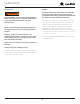
BLACK (BROWN) BLACK (BROWN) BI1215 ONLY OR WHITE (DARK BLUE) COND FAN WHITE ROCKER SWITCH 29 3 BROWN (ORANGE) 6 2 BLACK(BROWN) 3 6 1 4 6 2 3 1 5 4 O BROWN C N LIMIT SW MOLD HEATER 3 RPM MOTOR CAM C BIN SW NO NC LIGHT BLUE ALL OTHER MODELS BROWN NC NO C BLACK-HOT (SMOOTH) BLACK-NEUTRAL (RIBBED) 115 VOLT PLUG PLUG 220-240 VOLT EMBRACO COMPRESSOR RELAY NEUTRAL WHITE (DARK BLUE) BLACK (BROWN) OVERLOAD POWER CORD ASSEMBLY WHITE (DARK BLUE) EMU ONLY GROUND: GREEN or
U-Line Corporation (U-Line) Limited Warranty One Year Limited Warranty For one year from the date of original purchase, this warranty covers all parts and labor to repair or replace any part of the product that proves to be defective in materials or workmanship. For products installed and used for normal residential use, material cosmetic defects are included in this warranty, with coverage limited to 60 days from the date of original purchase.