USER GUIDE & SERVICE MANUAL 5 Class ● UHBD524 ● 24” Dual Zone Beverage Center
USER GUIDE & SERVICE MANUAL u-line.
USER GUIDE u-line.com WELCOME TO U-LINE Congratulations on your U-Line purchase. Your product comes from a company with over five decades of premium modular ice making, refrigeration, and wine preservation experience. U-Line continues to be the American leader, delivering versatility and flexibility for multiple applications including residential, light commercial, outdoor and marine use.
USER GUIDE u-line.com Safety and Warning ! DANGER NOTICE This unit contains R600a (Isobutane) which is a Please read all instructions before installing, flammable hydrocarbon. It is safe for regular operating, or servicing the appliance. use. Do not use sharp objects to expedite Use this appliance for its intended purpose only and follow these general precautions with those listed throughout this guide: defrosting.
USER GUIDE u-line.com Disposal and Recycling ! DANGER RISK OF CHILD ENTRAPMENT. Before you throw away your old refrigerator or freezer, take off the doors and leave shelves in place so children may not easily climb inside. If the unit is being removed from service for disposal, check and obey all federal, state, and local regulations regarding the disposal and recycling of refrigeration appliances, and follow these steps completely: 1. Remove all consumable contents from the unit. 2.
USER GUIDE u-line.com Environmental Requirements This model is intended for indoor/interior applications only and is not to be used in installations that are open/ exposed to natural elements. This unit is designed to operate between 50°F (10°C) and 100°F (38°C). Higher ambient temperatures may reduce the unit’s ability to reach low temperatures and/or reduce ice production on applicable models. For best performance, keep the unit out of direct sunlight and away from heat generating equipment.
USER GUIDE u-line.com Electrical ! WARNING SHOCK HAZARD — Electrical Grounding Required. Never attempt to repair or perform maintenance on the unit until the electricity has been disconnected. Never remove the round grounding prong from the plug and never use a two-prong grounding adapter. Altering, cutting or removing power cord, removing power plug, or direct wiring can cause serious injury, fire, loss of property and/or life, and will void the warranty.
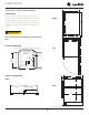
USER GUIDE u-line.com Cutout & Product Dimensions 23 5⁄8” (600 mm) PREPARE SITE Your U-Line product has been designed for either freestanding or built-in installation. When built-in, your unit FRONT does not require additional air space for top, sides, or 33 11⁄16” to 34 11⁄16” (855 mm to 881 mm) 28” (711 mm) rear. However, the front grille must NOT be obstructed, and clearance is required for an electrical connection in the rear.
USER GUIDE u-line.com Side-by-Side Installation OTHER SITE REQUIREMENTS Side-by-Side Installation Hinge-by-Hinge Installation (Mullion) When installing two units hinge-by-hinge, 13/16" (22 mm) is required for integrated models. Additional space may be needed for any knobs, pulls or handles installed. Units must operate from separate, properly grounded electrical receptacles placed according to each unit’s 13/16" (22 mm) electrical specifications requirements.
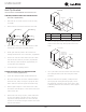
USER GUIDE u-line.com Anti-Tip Bracket Surrounding area (Top view) Use one of the methods below to secure the unit CABINET/COUNTER ANTI-TIP INSTALLATION (For built-in applications) 1. Back of unit Slide unit out so screws on front of unit are easily accessible. B Remove the two screws from the front of the unit. A 2. Back wall A CL Front of unit 5. 515 518 524 A 7 5⁄8” 9” 11 15⁄16” B 22” 22” 22” Place the anti-tip brackets on the floor against the line drawn for the outer edge.
USER GUIDE u-line.com General Installation INSTALLATION LEVELING INFORMATION 1. Use a level to 1. Plug in the power/electrical cord. 2. Gently push the unit into position. Be careful not to entangle the cord or water and drain lines, if confirm the unit is applicable. level. Level should 3. be placed along top Re-check the leveling, from front to back and side to edge and side edge side. Make any necessary adjustments. The unit’s top as shown.
USER GUIDE u-line.com Grille Installation REMOVING AND INSTALLING GRILLE ! WARNING Disconnect electric power to the unit before removing the grille. When using the unit, the grille must be installed. ! WARNING DO NOT touch the condenser fins. The condenser fins are SHARP and can be easily damaged. Removing the grille 1. Disconnect power to the unit. 2. Loosen the two screws (1). 3. Remove grille (2) from unit. Installing the grille 1.
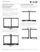
USER GUIDE u-line.com Door Swing Wall For Integrated models that are installed adjacent to a wall, 1/2" (13 mm) 1/2" (13 mm) clearance is recommended from wall on hinge side to allow the door to open 90°. Allow for additional space for any knobs or pulls installed on the integrated panel/frame. Stainless Steel models that are installed adjacent to a wall require 2-1/4" (57 mm) door clearance on hinge side to allow for door handle.
USER GUIDE Door Adjustments DOOR ALIGNMENT AND ADJUSTMENT Align and adjust the door if it is not level or not sealing u-line.com REVERSING THE DOOR 1. Open door. 2. Using T-25 Torx bit loosen screw #1 and remove screw #2 on top and bottom hinge. Slide and remove the properly. If the door is not sealed, the unit may not cool door from the unit. properly, or excessive frost or condensation may form in the interior.
USER GUIDE u-line.com First Use Initial startup requires no adjustments. When plugged in, the unit will begin operating under the factory default settings. If the unit was turned off during installation, simply press and the unit will immediately switch on. To turn the unit off, press . NOTICE Temperature displayed reflects actual temperature inside unit. If the temperature displayed is different than selected, the unit is progressing towards the selected temperature.
USER GUIDE u-line.com Control Operation CONTROL FUNCTION GUIDE FUNCTION COMMAND NOTES ON/OFF Press Unit will immediately turn On or OFF and release Interior light color indicates zone temperature being set; Blue = lower (38o - 65o) White = upper (38o - 65o) Adjust Temperatures Press or and release to adjust the lower zone. Press to change to upper zone. Press or and release to adjust. The upper temperature must be ≥ the lower temperature, maximum 20o higher.
USER GUIDE u-line.
USER GUIDE u-line.com Airflow & Product Loading NOTICE Restricting airflow may result in poor product AIRFLOW performance, product failure, and uneven External internal temperatures and may freeze contents.
USER GUIDE u-line.com Interior Adjustments 5. Once removed, retract the slides. Note: The slides on the rack have a thin coating which Dual Zone Beverage Centers feature side mounted rack is used to block moisture and provide lubrication. Use supports with 17 adjustment positions. care when handling. Dual Zone Beverage Centers ship with 2 wine racks, 1 Slide and Secure Storage Bin, and 1 slide out shelf. Installation Remove and reposition as desired. 1.
USER GUIDE u-line.com Wine Storage Options 3. Pull frame towards you until all pins are clear of the slots. If only repositioning the frame, do not remove WINE RACK BOTTLE POSITION completely - go to “Storage Bin Installation” Step 2. Specially designed horizontal wine racks properly position the bottles so the wine remains in contact with the cork, 4. Slightly tilt one side. Gently pull frame towards you to remove from unit. which ensures the cork does not become dry.
USER GUIDE Cleaning u-line.com To clean integrated panels, use household cleaner per the cabinet manufacturer’s recommendation. Stainless Models Stainless door panels and handles can discolor when exposed to chlorine gas, pool chemicals, saltwater or cleaners with bleach. Keep your stainless unit looking new by cleaning with a good quality all-in-one stainless steel cleaner and polish monthly. For best results use Claire® Stainless Steel INTERIOR CLEANING Disconnect power to the unit.
USER GUIDE u-line.com NOTICE The drain pan was not designed to capture the water created when manually defrosting. To prevent water from overflowing the drain pan and possibly damaging water sensitive flooring, the unit must be removed from cabinetry. To defrost: 1. Disconnect power to the unit. 2. Remove all products from the interior. 3. Prop the door in an open position (2 in. [50 mm] minimum). 4. Allow the frost to melt naturally. 5.
USER GUIDE u-line.com Cleaning Condenser INTERVAL - EVERY SIX MONTHS To maintain operational efficiency, keep the front grille free of dust and lint, and clean the condenser when necessary. Depending on environmental conditions, more or less frequent cleaning may be necessary. ! WARNING Disconnect electric power to the unit before cleaning the condenser. NOTICE DO NOT use any type of cleaner on the condenser unit. Condenser may be cleaned using a vacuum, soft brush, or compressed air. 1.
USER GUIDE u-line.com Extended Non-Use VACATION/HOLIDAY, PROLONGED SHUTDOWN The following steps are recommended for periods of extended non-use: 1. Remove all consumable content from the unit. 2. Disconnect the power cord from its outlet/socket and leave it disconnected until the unit is returned to service. 3. If ice is on the evaporator, allow ice to thaw naturally. 4. Clean and dry the interior of the unit. Ensure all water has been removed from the unit. 5.
USER GUIDE u-line.com Troubleshooting • Evaporator: Refrigerant flowing through an evaporator may sound like boiling liquid. BEFORE CALLING FOR SERVICE • Condenser Fan: Air moving through a condenser may be heard. • Automatic Defrost Drain Pan: Water may be heard dripping or running into the drain pan when the unit is in the defrost cycle. If you think your U-Line product is malfunctioning, read the CONTROL OPERATION section to clearly understand the function of the control.
USER GUIDE CHECKING PRODUCT TEMPERATURE u-line.com Causes which affect the internal temperatures of the cabinet include: • Temperature setting. • Ambient temperature where installed. • Installation in direct sunlight or near a heat source. • The number of door openings and the time the door is open. To check the actual product temperature in the unit: • The time the internal light is illuminated. (This mainly affects product on the top rack or shelf.) 1.
USER GUIDE u-line.com Product Liability Field service technicians are authorized to make an initial assessment in the event of reported damages. If there are any questions about the process involved, the technician should call U-Line for further explanation. While inspecting for defects or installation issues, photos should be taken to document any damages or issues found.
USER GUIDE Warranty Claims The following information defines the parameters for filing a warranty claim: Units must be registered prior to warranty submittal. Customers may register at www.U-Line.com. A proof of purchase is required. We also accept the following information to update warranty: • Valid serial number needed • Valid model number needed • Claims must be submitted online at www.U-LineService.com • u-line.
U-Line Corporation (U-Line) Limited Warranty One Year Limited Warranty For one year from the date of original purchase, this warranty covers all parts and labor to repair or replace any part of the product that proves to be defective in materials or workmanship. For products installed and used for normal residential use, material cosmetic defects are included in this warranty, with coverage limited to 60 days from the date of original purchase.