USER GUIDE & SERVICE MANUAL 1 Class ● UHFZ124 ● 24” Convertible Freezer
USER GUIDE & SERVICE MANUAL u-line.
USER GUIDE u-line.com WELCOME TO U-LINE Congratulations on your U-Line purchase. Your product comes from a company with over five decades of premium modular ice making, refrigeration, and wine preservation experience. U-Line creates products focused on functionality, style, and inspired innovations — paying close attention to even the smallest details. Applications include residential, outdoor, ADA height compliant, marine, and commercial.
USER GUIDE u-line.com Safety and Warning ! DANGER NOTICE This unit contains R600a (Isobutane) which is a Please read all instructions before installing, flammable hydrocarbon. It is safe for regular operating, or servicing the appliance. use. Do not use sharp objects to expedite Use this appliance for its intended purpose only and follow these general precautions with those listed throughout this guide: defrosting.
USER GUIDE u-line.com Disposal and Recycling ! DANGER RISK OF CHILD ENTRAPMENT. Before you throw away your old refrigerator or freezer, take off the doors and leave shelves in place so children may not easily climb inside. If the unit is being removed from service for disposal, check and obey all federal, state, and local regulations regarding the disposal and recycling of refrigeration appliances, and follow these steps completely: 1. Remove all consumable contents from the unit. 2.
USER GUIDE u-line.com Environmental Requirements This model is intended for indoor/interior applications only and is not to be used in installations that are open/ exposed to natural elements. This unit is designed to operate between 50°F (10°C) and 100°F (38°C). Higher ambient temperatures may reduce the unit’s ability to reach low temperatures and/or reduce ice production on applicable models. For best performance, keep the unit out of direct sunlight and away from heat generating equipment.
USER GUIDE u-line.com Electrical ! WARNING SHOCK HAZARD — Electrical Grounding Required. Never attempt to repair or perform maintenance on the unit until the electricity has been disconnected. Never remove the round grounding prong from the plug and never use a two-prong grounding adapter. Altering, cutting or removing power cord, removing power plug, or direct wiring can cause serious injury, fire, loss of property and/or life, and will void the warranty.
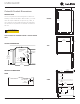
USER GUIDE u-line.com 23 15⁄16” (608 mm) Cutout & Product Dimensions PREPARE SITE Your U-Line product has been designed for either freestanding or built-in installation. When built-in, your unit FRONT does not require additional air space for top, sides, or 34 1⁄8” to 35 1⁄8” (867 mm to 892 mm) 28” (711 mm) rear. However, the front grille must NOT be obstructed, and clearance is required for an electrical connection in the rear.
USER GUIDE Side-by-Side Installation u-line.com 3. Place bracket over holes and attach to unit with two screws removed in step 2 using a T-25 Torx driver. Two units may be installed side-by-side. Cutout width for a side-by-side installation is the cutout Tighten screws fully. 4. Gently push units into position. Be careful not to dimension of a single unit times two. No trim kit is required. However, 1/4" (6 mm) of space entangle the electrical cord or water line, if applicable. 5.
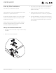
USER GUIDE u-line.com Anti-Tip Bracket 1. Slide unit out so screws on top of unit are easily accessible. 2. Remove the two screws from the opposite side of the hinge assembly using a T-25 Torx driver (see below). 3. Place bracket over holes and attach to unit with two screws removed in step 2 using a T-25 Torx driver. Tighten screws fully. 4. Gently push unit into position. Be careful not to entangle the electrical cord or water line, if applicable. 5.
USER GUIDE u-line.com General Installation INSTALLATION LEVELING INFORMATION 1. Use a level to 1. Plug in the power/electrical cord. 2. Gently push the unit into position. Be careful not to entangle the cord or water and drain lines, if confirm the unit is applicable. level. Level should 3. be placed along top Re-check the leveling, from front to back and side to edge and side edge side. Make any necessary adjustments. The unit’s top as shown.
USER GUIDE u-line.com Grille Installation REMOVING AND INSTALLING GRILLE ! WARNING Disconnect electric power to the unit before removing the grille. When using the unit, the grille must be installed. ! WARNING DO NOT touch the condenser fins. The condenser fins are SHARP and can be easily damaged. Removing the grille 1. Disconnect power to the unit. 2. Loosen the two screws (1). 3. Remove grille (2) from unit. Installing the grille 1.
USER GUIDE u-line.com Door Swing Wall 2-1/8" Min. (54 mm) 90° Door Swing Units have a zero clearance for the door to open 90°, when installed adjacent to cabinets. Stainless Steel models require 2-1/8" (54 mm) door clearance to accommodate the handle if installed next to a wall.
USER GUIDE u-line.com Door Adjustments REVERSING THE DOOR HINGE COVER Location of the unit may make it desirable to mount the Hinge cover included with the literature bag is optional. door on the opposite side of the cabinet. The hinge hardware will be removed and reinstalled on the opposite side of the cabinet. To install hinge cover: 1. Press hinge cover squarely over hinge.
USER GUIDE 3. Remove door by tilting forward and lifting door off u-line.com Install top hinge and door: bottom hinge. Retain shoulder washers; they will be reused. 4. 1. Remove three screws from hinge holes on the Install hinge with longer straight edge aligned to outside edge of cabinet. Do not tighten. opposite side. Reinstall into holes where the hinge was removed. (If utilizing supplied screw cover, install just one screw.) Remove bottom hinge: 1.
USER GUIDE u-line.com Free Standing Kit Te free standing kit is an optional accessory (ULAFREESTANDS), used when unit is freestanding - not built into a cabinet. Available at u-line.com. To install the kit: 1. Remove grille (see GRILLE INSTALLATION section). 3. Align front hole wit hole in shell accessory, hole in base, and hole in grille. Tighten screw. 2. Place shell accessory over front and back of cabinet base, aligning holes of shell accessory with the holes on the base.
USER GUIDE u-line.com First Use Initial startup requires no adjustments. If the unit was turned off, press and the unit will immediately switch on. To turn off, press and release. See CONTROL OPERATION section for more details. NOTICE Temperature displayed reflects actual temperature inside unit. If the temperature displayed is different than selected, the unit is progressing towards the selected temperature.
USER GUIDE u-line.com Control Operation CONTROL FUNCTION GUIDE FUNCTION COMMAND NOTES ON/OFF Press Unit will immediately turn On or OFF Press Leave interior light on and release and release to leave interior light on for 12 hours; press again to After 12 hours, factory default is restored; light will turn on when door is open deactivate When the display is flashing, press Adjust Temperature Press or and release or to adjust the set point temperature.
USER GUIDE u-line.com SAFETY • INSTALLATION & INTEGRATION • OPERATING INSTRUCTIONS • MAINTENANCE • SERVICE Airflow and Product Loading NOTICE The unit requires proper airflow to perform at its highest efficiency. Do not block the front grille, internal fans or vents at any time, or the unit will not perform as expected. Do not install the unit behind a door.
USER GUIDE Interior Adjustments FREEZER BASKETS Freezer Basket Installation & Removal u-line.com NOTICE Do not remove the track rails from the cabinet. To reinstall: 1. Align the left and right basket channels with the tracks in the cabinet. Ensure an even track engagement on Freezer baskets are removable for cleaning. To remove both sides by gently pushing the basket into the the baskets follow the instructions below. cabinet until it stops. 2.
USER GUIDE Cleaning u-line.com To clean integrated panels, use household cleaner per the cabinet manufacturer’s recommendation. Stainless Models Stainless door panels and handles can discolor when exposed to chlorine gas, pool chemicals, saltwater or cleaners with bleach. Keep your stainless unit looking new by cleaning with a good quality all-in-one stainless steel cleaner and polish monthly. For best results use Claire® Stainless Steel INTERIOR CLEANING Disconnect power to the unit.
USER GUIDE u-line.com NOTICE The drain pan was not designed to capture the water created when manually defrosting. To prevent water from overflowing the drain pan and possibly damaging water sensitive flooring, the unit must be removed from cabinetry. To defrost: 1. Disconnect power to the unit. 2. Remove all products from the interior. 3. Prop the door in an open position (2 in. [50 mm] minimum). 4. Allow the frost to melt naturally. 5.
USER GUIDE u-line.com Cleaning Condenser INTERVAL - EVERY SIX MONTHS To maintain operational efficiency, keep the front grille free of dust and lint, and clean the condenser when necessary. Depending on environmental conditions, more or less frequent cleaning may be necessary. ! WARNING Disconnect electric power to the unit before cleaning the condenser. NOTICE DO NOT use any type of cleaner on the condenser unit. 1. Remove the grille. 2.
USER GUIDE u-line.com Extended Non-Use VACATION/HOLIDAY, PROLONGED SHUTDOWN The following steps are recommended for periods of extended non-use: 1. Remove all consumable content from the unit. 2. Disconnect the power cord from its outlet/socket and leave it disconnected until the unit is returned to service. 3. If ice is on the evaporator, allow ice to thaw naturally. 4. Clean and dry the interior of the unit. Ensure all water has been removed from the unit. 5.
USER GUIDE u-line.com Troubleshooting • Evaporator: Refrigerant flowing through an evaporator may sound like boiling liquid. BEFORE CALLING FOR SERVICE • Condenser Fan: Air moving through a condenser may be heard. • Automatic Defrost Drain Pan: Water may be heard dripping or running into the drain pan when the unit is in the defrost cycle. If you think your U-Line product is malfunctioning, read the CONTROL OPERATION section to clearly understand the function of the control.
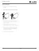
USER GUIDE CHECKING PRODUCT TEMPERATURE u-line.com Causes which affect the internal temperatures of the cabinet include: • Temperature setting. • Ambient temperature where installed. • Installation in direct sunlight or near a heat source. • The number of door openings and the time the door is open. To check the actual product temperature in the unit: • The time the internal light is illuminated. (This mainly affects product on the top rack or shelf.) 1.
USER GUIDE u-line.com Product Liability Field service technicians are authorized to make an initial assessment in the event of reported damages. If there are any questions about the process involved, the technician should call U-Line for further explanation. While inspecting for defects or installation issues, photos should be taken to document any damages or issues found.
USER GUIDE Warranty Claims The following information defines the parameters for filing a warranty claim: Units must be registered prior to warranty submittal. Customers may register at www.U-Line.com. A proof of purchase is required. We also accept the following information to update warranty: • Valid serial number needed • Valid model number needed • Claims must be submitted online at www.U-LineService.com • u-line.
USER GUIDE u-line.com Ordering Replacement Parts Parts may be ordered online at www.U-Line.com See our contact information below: www.U-LineService.com (with service login) Phone Number: +1.800.779.2547 NOTICE Use only genuine U-Line replacement parts. The use of non-U-Line parts can reduce speed of ice production, cause water to overflow from ice maker mold, damage the unit, and void the warranty. Warranty parts will be shipped at no charge after U-Line confirms warranty status.
USER GUIDE u-line.
USER GUIDE u-line.com SAFETY • INSTALLATION & INTEGRATION • OPERATING INSTRUCTIONS • MAINTENANCE • SERVICE Compressor Specifications Electrical Relay and Overload Protector EM3D50HLT ! DANGER Refrigerant R134a Voltage 115 - 127 VAC Electrocution can cause death or serious injury. Frequency Burns from hot or cold surfaces can cause Run Cap serious injury. Take precautions when servicing Start Winding 5.95 Ohm at 77°F/25°C Run Winding 5.35 Ohm at 77°F/25°C this unit.
USER GUIDE Troubleshooting - Extended ! CAUTION Never attempt to repair or perform maintenance on the unit until the main electrical power has been disconnected from the unit. u-line.com NORMAL OPERATING SOUNDS All models incorporate rigid foam insulated cabinets to provide high thermal efficiency and maximum sound reduction for its internal working components. Despite this technology, your model may make sounds that are unfamiliar.
USER GUIDE u-line.com TROUBLESHOOTING GUIDE Concern Potential Causes Action Not Cooling Compressor overheating Verify proper air flow through condenser. Is condenser clean? Confirm condenser fan operation. Frozen Product Frost Buildup Inside Unit Display Not Working Compressor not operating Test overload and relay, replace as needed. Compressor operating - no cooling Refer to System Diagnosis Guide. Control set too cold Adjust Set Point Temp accordingly.
USER GUIDE u-line.com MAIN CONTROL ! CAUTION The main control board is very robust and is rarely the cause of system issues. It is important to fully diagnose the board for any suspected failures before attempting to remove the board for replacement or service. Follow the guidelines below to fully test and diagnose the main control. Precautions must be taken while working with live electrical equipment. Be sure to follow proper safety procedures while performing tests on live systems.
USER GUIDE u-line.com Control Operation-Service UI BUTTON LAYOUT USER GUIDE 1. Up Button SAFETY • INSTALLATION & INTEGRATION • OPERATING -Increases temperature -Navigates through service menu -LED activated with button activation 2.
To view the thermistor temperature, push and release the DISPLAY/OPTIONS up and down keys. The display will show the corrected USER GUIDE Unit will immediately turn ON or OFF refrigerator temperature. ve interior light Glass door wine captains and beverage centers only. SHOWROOM MODE When the “F” or “C” in the display is flashing, This mode is designed to show units in a display environpush to adjust the set point or ment. When in this mode the only functions will be the temperature.
USER GUIDE u-line.com ERATING INSTRUCTIONS • MAINTENANCE • SERVICE SERVICE MODE GUIDE 1. THERMISTOR 1 — ZONE This shows the pure thermistor reading with no offsets taken into account. 2. THERMISTOR 2 — EVAPORATOR This shows the pure thermistor reading with no offsets taken into account. 3. Does not apply to this model. 4. Does not apply to this model. USER GUIDE u-line.com SAFETY • INSTALLATION & INTEGRATION • OPERATIN 14.
USER GUIDE u-line.com u-line.com OPERATING INSTRUCTIONS • MAINTENANCE • SERVICE 20. MODEL NUMBER INDICATOR Displays the two-digit model number of the specific unit. See model list table. 21. LIGHT ALL LED SEGMENTS This will illuminate all the LEDs on the display to ensure they work properly. 22. VIEW DEFROST CYCLES Displays the number of defrosts that have occurred in the past 24 hours. 23.
USER GUIDE USER GUIDE u-line.com u-line.
Control Operation-Service N/A N/A N/A Ice Maker 2 N/A N/A 1224WC ADA24R CLR1215 CO1224F 2218R 2218RGL 40 vl2 N/A N/A Defrost Heater N/A N/A N/A N/A N/A N/A N/A N/A N/A N/A N/A 2224ZWC 2245R 2245RDC 2245WC 2260DC 2260R 2260RDC 2260WC 2260ZWC 1224FZR N/A N/A N/A N/A Hot Gas Valve Hot Gas Valve Hot Gas Valve N/A N/A N/A N/A N/A N/A N/A N/A N/A vl2 N/A N/A N/A 2224WC N/A N/A N/A N/A N/A N/A N/A N/A Pan Heater Water Valve N/A N/A N/A Pan Heat
USER GUIDE u-line.com Thermistors Evaporator Thermistor Thermistors are used for various temperature readings. If the evaporator thermistor fails, the unit will rely on a Thermistors provide reliable temperature readings preset defrost timer during defrost cycles. The unit will USER GUIDE using a resistance which varies based on surrounding u-line.com otherwise operate normally. Refer to defrost section. temperatures.
USER GUIDE u-line.com Defrost This unit defrosts every 12 hours of compressor runtime for 45 minutes. If you have verified that the unit does not have an ambient air leak, utilize the Control Operation - Service section and adjust unit to defrost every 9 hours for 60 minutes. Also, adjust the #2 thermistor to -4 instead of 0.
USER GUIDE Remove Fan and Cover u-line.com 6. Remove insulating foam from refrigerant line passthrough hole as needed to gain clearance for fan plug. CONVECTION COOLING This unit is equipped with an advanced convection cooling system. Convection cooling stabilizes cabinet temperature, cools product faster and increases energy efficiency. Evaporator Fan The evaporator fan is responsible for circulating warm air 7. Remove internal shelving. 8. Remove rear shelf clips, fronts can remain. 9.
USER GUIDE u-line.com 14. Remove and replace fan. Take special care to properly route fan wire. NOTICE Fan must be oriented to pull air in through lower evaporator cover vents and push air out at fan mounting location. 15. Installation is the reverse of removal. 16. Care must be taken to assure the bottom of the evaporator cover is reinstalled behind the front edge of the train trough. 17. Use sealant gum to seal any openings at rear of unit before replacing rear cover. 18.
U-Line Corporation (U-Line) Limited Warranty One Year Limited Warranty For one year from the date of original purchase, this warranty covers all parts and labor to repair or replace any part of the product that proves to be defective in materials or workmanship. For products installed and used for normal residential use, material cosmetic defects are included in this warranty, with coverage limited to 60 days from the date of original purchase.