USER GUIDE & SERVICE MANUAL Marine Series ● UMCR014 ● 14” Crescent Ice Maker (115V)
USER GUIDE & SERVICE MANUAL u-line.
USER GUIDE u-line.com WELCOME TO U-LINE Congratulations on your U-Line purchase. Your product comes from a company with over five decades of premium modular ice making, refrigeration, and wine preservation experience. U-Line creates products focused on functionality, style, and inspired innovations — paying close attention to even the smallest details. Applications include residential, outdoor, ADA height compliant, marine, and commercial.
USER GUIDE u-line.com Safety and Warning ! DANGER NOTICE This unit contains R600a (Isobutane) which is a Please read all instructions before installing, flammable hydrocarbon. It is safe for regular operating, or servicing the appliance. use. Do not use sharp objects to expedite Use this appliance for its intended purpose only and follow these general precautions with those listed throughout this guide: defrosting.
USER GUIDE u-line.com Disposal and Recycling ! DANGER RISK OF CHILD ENTRAPMENT. Before you throw away your old refrigerator or freezer, take off the doors and leave shelves in place so children may not easily climb inside. If the unit is being removed from service for disposal, check and obey all federal, state, and local regulations regarding the disposal and recycling of refrigeration appliances, and follow these steps completely: 1. Remove all consumable contents from the unit. 2.
USER GUIDE u-line.com Environmental Requirements This model is intended for indoor/interior applications only and is not to be used in installations that are open/ exposed to natural elements. This unit is designed to operate between 50°F (10°C) and 100°F (38°C). Higher ambient temperatures may reduce the unit’s ability to reach low temperatures and/or reduce ice production on applicable models. For best performance, keep the unit out of direct sunlight and away from heat generating equipment.
USER GUIDE u-line.com Electrical ! WARNING SHOCK HAZARD — Electrical Grounding Required. Never attempt to repair or perform maintenance on the unit until the electricity has been disconnected. Never remove the round grounding prong from the plug and never use a two-prong grounding adapter. Altering, cutting or removing power cord, removing power plug, or direct wiring can cause serious injury, fire, loss of property and/or life, and will void the warranty.
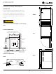
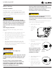
USER GUIDE u-line.com Cutout & Product Dimensions 14 1⁄8” (356 mm) 3⁄4” PREPARE SITE (19 mm) Your U-Line product has been designed for either freestanding or built-in installation. When built-in, your unit 4 11⁄16” (119 mm) Flange sides and bottom does not require additional air space for top, sides, or 11⁄16” rear. However, the front grille must NOT be obstructed, and clearance is required for an electrical connection in 24 11⁄16” (627 mm) (17 mm) FRONT the rear.
USER GUIDE u-line.com Water Hookup Failure to follow recommendations and PREPARE PLUMBING flooding or void the product warranty. The water valve uses a standard 1/4” (6.35 mm) Use new hose set. Do not reuse old hose set. instructions may result in damage and/or harm, compression fitting. U-Line recommends using accessory water hook up kit – part # ULAWATERHOOKUP. The kit ! CAUTION includes a 10’ (3 m) braided flexible water supply line and a brass hose fitting.
USER GUIDE u-line.com General Installation LEVELING INFORMATION NOTICE Because these units do not have leveling legs, it is extremely important that they sit on a level surface. If they are not level, the ice mold will not fill evenly. Use a level to confirm the unit is level. Level should be placed along top edge and side edge as shown. INSTALLATION 1. Plug in the power/electrical cord. 2. Gently push the unit into position. Be careful not to entangle the cord or water line. 3.
USER GUIDE u-line.com Grille Installation REMOVING AND INSTALLING GRILLE ! WARNING Disconnect electric power to the unit before removing the grille. When using the unit, the grille must be installed. ! WARNING DO NOT touch the condenser fins. The condenser fins are SHARP and can be easily damaged. Removing the grille 1. Disconnect power to the unit. 2. Open unit door. 3. Remove the center screw. 4. Remove grille by sliding grille up and pulling it toward you. 3 Installing the grille 1.
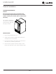
USER GUIDE 16-1/2" 16-1/2" u-line.com 90° Door Swing 90° Door Swing Door Swing Stainless Steel Black, White and Wood Overlay 2175R(F) & 2275WC Models Wall Wall 1/4" Min. (6 mm) 2-1/8" Min. (54 mm) 90° Door Swing 90° Door Swing Stainless Steel, Black and White Integrated 2175BEV This unit requires zero clearance for the door to open 90o Wall when adjacent 2-1/8" to cabinets. 1/4" Min. installed Min.
USER GUIDE Door Adjustments u-line.com 3. bottom hinge. Retain shoulder washers; they will be DOOR ALIGNMENT AND ADJUSTMENT Align and adjust the door if it is not level or is not sealing properly. If the door is not sealed, the unit may not cool reused. 4. 5. Install three screws into holes where the hinge was removed. Properly aligned, the door’s gasket should be firmly in contact with the cabinet all the way around the door (no gaps). Carefully examine the Move bottom hinge: 1.
USER GUIDE 3. u-line.com Remove plastic plug on top of door and save for reinstallation on opposite side. 4. Relocate plastic bushings on top and bottom of door to opposite side. Clean out bushing hole in door bottom with a screwdriver if necessary. Hinge Plastic Hole Plug Plastic Hole Plug Screw Right Side Door Swing Left Side Door Swing Right Side Invert Hinge Screw Invert Hinge Install top hinge: 1. Remove pivot screw from top hinge, invert screw and reinstall pivot screw in top hinge. 2.
USER GUIDE u-line.com Door Latch The door latch assembly included with your unit can be installed to prevent the door from opening when the vehicle is in motion. To install, perform the following: 1. Remove the two outer most screws from the nonhinge side. 2. Place spacer (2) over mounting holes. Place latch (1) on top of spacer (2). Note: Spacer (2) only required if included with unit. 3. Re-install the screws, but do not tighten all the way. 4.
USER GUIDE u-line.com First Use Initial startup requires no adjustments. NOTICE U-Line recommends discarding the ice produced during the first two to three hours of operation to avoid possible dirt or scale that may dislodge from the water line. ON OFF To turn the unit on or off: Press the rocker switch located inside the door on the front panel, or behind the grille.
USER GUIDE u-line.com Ice ! CAUTION ICE MAKER OPERATION When the ice bucket is full, the ice making mechanism will shut off. However, the refrigeration system will continue to cool and maintain the ice supply. NEVER use an ice pick, knife or other sharp instrument to separate cubes. Shake the ice bucket instead. During periods of limited use or high ambient NOTICE temperatures, it is common for cubes to fuse together.
USER GUIDE u-line.com ICE MAKER ADJUSTMENT 3. Turn the adjusting screw toward the minus (-) sign (clockwise) for smaller cubes or toward the plus (+) Ice Cube Thickness Adjustment sign (counterclockwise) for larger cubes. Interval - As Required On ice maker equipped models, adjust the cube size by 4. Install the ice maker assembly cover. changing water amount injected into the ice maker assembly as follows: ADJUSTING ICE HARVEST 1. Remove the front grille (see GRILLE INSTALLATION). 2.
USER GUIDE u-line.com Airflow and Product Loading NOTICE The unit requires proper airflow to perform at its highest efficiency. Do not block the front grille at any time, or the unit will not perform as expected. Do not install the unit behind a door. Depending on the model, your grille may not match exactly with the below illustrations. USER GUIDE u-line.
USER GUIDE u-line.com Cleaning If any surface discoloring or rusting appears, clean it EXTERIOR CLEANING and a nonabrasive cloth. Always clean with the grain. Vinyl Clad (Black or White) Models Always finish with Claire® Stainless Steel Polish and Clean surfaces with a mild detergent and warm water solution. Do not use solvent-based or abrasive cleaners. quickly with Bon-Ami® or Barkeepers Friend Cleanser® Cleaner or comparable product to prevent further problems.
USER GUIDE u-line.com DEFROSTING NOTICE Manual Defrost Models DO NOT clean ice bucket using a dishwasher. The This unit is a manual defrost model and will require bucket is not dishwasher safe and will be occasional defrosting. When there is build-up of 1/4" damaged. (6 mm) or more of frost, manually defrost the unit. 10.When the interior is dry, reconnect power and turn unit on. ! CAUTION DO NOT use an ice pick or other sharp instrument to help speed up defrosting.
USER GUIDE u-line.com Extended Non-Use VACATION/HOLIDAY, PROLONGED SHUTDOWN For questions regarding winterization, please call U-Line at 414.354.0300. The following steps are recommended for periods of extended non-use: 1. ! CAUTION Remove all consumable content from the unit. Damage caused by freezing temperatures is not 2. Disconnect the power cord from its outlet/socket and leave it disconnected until the unit is returned to service. 3. Turn off the water supply. 4.
USER GUIDE u-line.com SAFETY • INSTALLATION & INTEGRATION • OPERATING INSTRUCTIONS • MAINTENANCE • SERVICE Troubleshooting • Evaporator: Refrigerant flowing through an evaporator may sound like boiling liquid. BEFORE CALLING FOR SERVICE If you think your U-Line product is malfunctioning, read • Condenser Fan: Air moving through a condenser may the CONTROL OPERATION section to clearly understand be heard. the function of the control.
USER GUIDE u-line.com SAFETY • INSTALLATION & INTEGRATION • OPERATING INSTRUCTIONS • MAINTENANCE • SERVICE Problem Possible Cause and Remedy Product is Not Cold Enough. Air temperature does not indicate product temperature. See CHECKING PRODUCT TEMPERATURE below. Adjust the temperature to a cooler set point. Ensure unit is not located in excessive ambient temperatures or in direct sunlight. Ensure the door is closing and sealing properly. Ensure the interior light has not remained on too long.
BLACK (BROWN) BLACK (BROWN) BI1215 ONLY OR WHITE (DARK BLUE) COND FAN WHITE ROCKER SWITCH 25 3 BROWN (ORANGE) 6 2 BLACK(BROWN) 3 6 1 4 6 2 3 1 5 4 O BROWN C N LIMIT SW MOLD HEATER 3 RPM MOTOR CAM C BIN SW NO NC LIGHT BLUE ALL OTHER MODELS BROWN NC NO C BLACK-HOT (SMOOTH) BLACK-NEUTRAL (RIBBED) 115 VOLT PLUG PLUG 220-240 VOLT EMBRACO COMPRESSOR RELAY NEUTRAL WHITE (DARK BLUE) BLACK (BROWN) OVERLOAD POWER CORD ASSEMBLY WHITE (DARK BLUE) EMU ONLY GROUND: GREEN or
USER GUIDE u-line.com SAFETY • INSTALLATION & INTEGRATION • OPERATING INSTRUCTIONS • MAINTENANCE • SERVICE Product Liability Field service technicians are authorized to make an initial assessment in the event of reported damages. If there are any questions about the process involved, the technician should call U-Line for further explanation. While inspecting for defects or installation issues, photos should be taken to document any damages or issues found.
USER GUIDE u-line.com SAFETY • INSTALLATION & INTEGRATION • OPERATING INSTRUCTIONS • MAINTENANCE • SERVICE Warranty Claims warranty status.
Parts ULN-WH95FC-03A Item 23 1 14 27 18 16 12 15 22 10 9 17 8 3 4 21 7 Description U-Line P/N 1 Back panel 80-54614-00 2 Compression nut/sleeve 80-54355-00 3 Compressor electricals only 80-54377-00 4 Compressor w/electricals 80-54376-00 5 Condenser assembly 80-54601-00 6 Condenser fan blade 80-54379-00 7 Condenser fan motor 80-54378-00 8 Control Assembly 80-54590-00 9 Door assembly w/o hinges 80-54662-00 10 Gasket, door 80-54617-00 11 Drier 80-54055-00 12 Evap/cabi
USER GUIDE u-line.com SAFETY • INSTALLATION & INTEGRATION • OPERATING INSTRUCTIONS • MAINTENANCE • SERVICE Ordering Replacement Parts If you have a purchasing account, please utilize our service website to order parts. Orders may also be placed by Fax or phone. See our contact information below: www.U-LineService.com (with service login) FAX Number: +1.414.354.5696 Phone Number: +1.800.779.2547 NOTICE Use only genuine U-Line replacement parts.
USER GUIDE u-line.
USER GUIDE u-line.com SAFETY • INSTALLATION & INTEGRATION • OPERATING INSTRUCTIONS • MAINTENANCE • SERVICE Compressor Specifications ! DANGER OVERLOAD PROTECTOR Electrocution can cause death or serious injury. Burns from hot or cold surfaces can cause serious injury. Take precautions when servicing R S C this unit. STARTING RELAY Disconnect the power source. RELAY COVER ULIN_0576_AW Do not stand in standing water when working around electrical appliances.
USER GUIDE u-line.com SAFETY • INSTALLATION & INTEGRATION • OPERATING INSTRUCTIONS • MAINTENANCE • SERVICE Troubleshooting - Extended SPECIFIC ERRORS & ISSUES ! CAUTION Never attempt to repair or perform maintenance on the unit until the main electrical power has been disconnected from the unit. TROUBLESHOOTING GUIDE Concern Potential Causes Suggested Remedy Will not eject ice (water frozen). Control setting too cold. Adjust control warmer (counterclockwise).
USER GUIDE u-line.com SAFETY • INSTALLATION & INTEGRATION • OPERATING INSTRUCTIONS • MAINTENANCE • SERVICE Concern Potential Causes Suggested Remedy Not freezing (compressor and fans not operating). Power cord not plugged in. Plug in power cord. On/Off switch in off position. Turn switch to on position. On/Off switch inoperable (open). Replace On/Off switch. Compressor overheating. Compressor will not stop operating. Water leak (under unit). Water leak (inside unit). Excessive frost buildup.
USER GUIDE u-line.
USER GUIDE u-line.com SAFETY • INSTALLATION & INTEGRATION • OPERATING INSTRUCTIONS • MAINTENANCE • SERVICE ICE MAKER OPERATING CYCLES Freeze Cycle • Temperature control terminals 2 and 3 are closed. • Power to the condenser. • Power to the condenser fan. black ON OFF SWITCH black black FAN MOTOR ground brown black COMP. START RELAY OVER LOAD WATER VALVE black blue HOLD C SWITCH LIMIT SWITCH NC WATER C FILL SWITCH black NO yellow NC 2 3 black white ICE MAKER MOTOR TEMP.
USER GUIDE u-line.com SAFETY • INSTALLATION & INTEGRATION • OPERATING INSTRUCTIONS • MAINTENANCE • SERVICE Harvest-1 Cycle • Temperature control terminals 2 and 3 are open - 2 and 1 close. • No power to the compressor or condenser fan. • If bin arm is down, power goes through bin arm switch to the ice maker motor. If bin arm is up, the ice maker will not harvest. black ON OFF SWITCH black black FAN MOTOR ground brown black COMP.
USER GUIDE u-line.com SAFETY • INSTALLATION & INTEGRATION • OPERATING INSTRUCTIONS • MAINTENANCE • SERVICE HARVEST-2 CYCLE • Ice maker ejector blades reach approximately 2:00 position and cam depresses the hold switch. Power goes through the hold switch to the ice maker motor and mold heater. • Ejector blades stall on ice and ice maker motor pulsates until mold heater warms and ice releases. black ON OFF SWITCH black black FAN MOTOR ground brown black COMP.
USER GUIDE u-line.com SAFETY • INSTALLATION & INTEGRATION • OPERATING INSTRUCTIONS • MAINTENANCE • SERVICE WATER FILL CYCLE • Ice maker ejector blades reach approximately 10:00 position and cam depresses the water fill switch. • Power to the water valve. Ice maker mold fills. black ON OFF SWITCH black black FAN MOTOR ground brown black COMP.
USER GUIDE u-line.com SAFETY • INSTALLATION & INTEGRATION • OPERATING INSTRUCTIONS • MAINTENANCE • SERVICE TEMPERATURE CONTROL SPECIFICATIONS Double Throw Ice Maker Thermostat Numbers 4548, AR-19-12, 2636, 2690, 2691, 2717, 2783, 2782-S, 2763-S, 2780, 80-26005-02 . These temperature controls are double throw, single pole controls. The sensing tube is inserted into the ice maker mold and senses mold temperature.
USER GUIDE u-line.com SAFETY • INSTALLATION & INTEGRATION • OPERATING INSTRUCTIONS • MAINTENANCE • SERVICE LIMIT SWITCH SPECIFICATIONS • Normally closed Bi-metal switch • Open temperature: 104°F • Close temperature: 83°F The function of this switch is to open in the event of an overheating condition. This bi-metal thermostat is normally closed and does not initiate the ice harvest cycle.
USER GUIDE u-line.com SAFETY • INSTALLATION & INTEGRATION • OPERATING INSTRUCTIONS • MAINTENANCE • SERVICE 8. Remove ice maker assembly. REPLACING ICE MAKER ASSEMBLY (CO29F ONLY) 1. Unplug the unit from the main power source. 9. Place new ice maker assembly into position and secure with three screws (5). 2. Disconnect ice maker wire harness at plug (1). 10.Reconnect wire harness at plug. 3. Remove control capillary tube from sensing tube on ice maker assembly (2). 11.
USER GUIDE u-line.com SAFETY • INSTALLATION & INTEGRATION • OPERATING INSTRUCTIONS • MAINTENANCE • SERVICE 17.Mount the back panel. REPLACING ICE MAKER ASSEMBLY (ALL MODELS EXCEPT CO29F) 1. Remove back panel. 18.Plug in unit and test. 2. Disconnect all wires at bell connectors (5 wires-Models 220 Volt Conversion List BI95, BI98 or SP18; or Plug-Models). All models listed in this manual are equipped to run on 110/115 volt. This document is a conversion list for the 3.
USER GUIDE u-line.com SAFETY • INSTALLATION & INTEGRATION • OPERATING INSTRUCTIONS • MAINTENANCE • SERVICE Defrost These units are manual defrost. To defrost unit remove ice bucket. Turn unit off. Use toweling inside to absorb water as it melts down. This will help prevent water from getting onto customer’s floor. The defrost duration is dependent upon usage or climate. Typically, defrosting is needed approximately every 3 - 6 weeks and/or when 1/4" or more of frost is present whichever comes first.
U-Line Corporation (U-Line) Limited Warranty One Year Limited Warranty For one year from the date of original purchase, this warranty covers all parts and labor to repair or replace any part of the product that proves to be defective in materials or workmanship. For products installed and used for normal residential use, material cosmetic defects are included in this warranty, with coverage limited to 60 days from the date of original purchase.