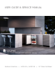
USER GUIDE & SERVICE MANUAL Outdoor Collection ● UOCL115 / UOCP115 ● 15” Clear Ice Maker
USER GUIDE u-line.
USER GUIDE u-line.com WELCOME TO U-LINE Congratulations on your U-Line purchase. Your product comes from a company with over five decades of premium modular ice making, refrigeration, and wine preservation experience. U-Line continues to be the American leader, delivering versatility and flexibility for multiple applications including residential, light commercial, outdoor and marine use.
USER GUIDE u-line.com Safety and Warning ! WARNING NOTICE CALIFORNIA PROPOSITION 65 Please read all instructions before installing, This product contains chemicals known to the operating, or servicing the appliance. state of California to cause cancer and birth defects or other reproductive harm. Use this appliance for its intended purpose only and follow www.P65warnings.CA.
USER GUIDE u-line.com Disposal and Recycling ! DANGER RISK OF CHILD ENTRAPMENT. Before you throw away your old refrigerator or freezer, take off the doors and leave shelves in place so children may not easily climb inside. If the unit is being removed from service for disposal, check and obey all federal, state, and local regulations regarding the disposal and recycling of refrigeration appliances, and follow these steps completely: 1. Remove all consumable contents from the unit. 2.
USER GUIDE u-line.com Environmental Requirements This unit is designed to operate between 50°F (10°C) and 100°F (38°C). Higher ambient temperatures may reduce the unit’s ability to reach low temperatures and/or reduce ice production on applicable models. For best performance, keep the unit out of direct sunlight and away from heat generating equipment. In climates where high humidity and dew points are present, condensation may appear on outside surfaces. This is considered normal.
USER GUIDE u-line.com Electrical ! WARNING SHOCK HAZARD — Electrical Grounding Required. Never attempt to repair or perform maintenance on the unit until the electricity has been disconnected. Never remove the round grounding prong from the plug and never use a two-prong grounding adapter. Altering, cutting or removing power cord, removing power plug, or direct wiring can cause serious injury, fire, loss of property and/or life, and will void the warranty.
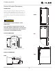
USER GUIDE u-line.com Cutout & Product Dimensions 14 15⁄16” (379 mm) PREPARE SITE Your U-Line product has been designed for either freestanding or built-in installation. When built-in, your unit does not require additional air space for top, sides, or rear. However, the front grille must NOT be obstructed, FRONT and clearance is required for an electrical connection in 28” (711 mm) the rear.
USER GUIDE Side-by-Side Installation u-line.com 3. Place bracket over holes and attach to unit with two screws removed in step 2 using a T-25 Torx driver. Two units may be installed side-by-side. Cutout width for a side-by-side installation is the cutout Tighten screws fully. 4. Gently push units into position. Be careful not to dimension of a single unit times two. No trim kit is required. However, 1/4" (6 mm) of space entangle the electrical cord or water line, if applicable. 5.
USER GUIDE u-line.com Water Hookup ! CAUTION PREPARE PLUMBING The water valve uses a standard 1/4” (6.35 mm) compression fitting. U-Line recommends using accessory water hookup kit Part # 80-54674-00. The kit includes a 10’ (3 m) braided Do not use any plastic water supply line. The line is under pressure at all times. Plastic may crack or rupture with age and cause damage to your home. flexible water supply line and a brass hose fitting.
USER GUIDE u-line.com 3. Locate water 8. Install retaining clip. valve in the front of the unit and thread water supply line through. NOTICE Route the water supply line through the unit so it does not come into contact with any internal components other than the solenoid valve. Normal operation creates some vibration. A water supply line contacting an internal component or cabinet wall can cause excessive noise during operation or damage to the line. 4.
USER GUIDE Drain u-line.com GRAVITY DRAIN Model numbers including “CL” or “NB” do not include a factory installed drain pump. Normal Proper Drain Model numbers including “CP” or “NP” include a factory installed drain pump. With Trap Poor Drainage, Water Will Back Up DRAIN CONNECTION ! CAUTION With Trap and Vent Proper Drain If your U-Line unit did not come with a factory installed drain pump you must use a gravity style drain connection.
USER GUIDE u-line.com FACTORY INSTALLED DRAIN PUMP Y-Branch Tailpiece P60 Pump Required If your drain line will run up to a stand pipe, disposal or Air Gap (Optional Hook-Up) spigot assembly, or does not otherwise meet the requirements for a gravity drain, you may have ordered a pre-installed U-Line P60 drain pump. Waste If you need to install a P60 drain pump into your unit, see 6KXW 2ɞ Valve DRAIN PUMP section in the User Manual.
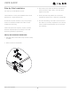
USER GUIDE u-line.com Anti-Tip Bracket 1. Slide unit out so screws on top of unit are easily accessible. 2. Remove the two screws from the opposite side of the hinge assembly using a T-25 Torx driver (see below). 3. Place bracket over holes and attach to unit with two screws removed in step 2 using a T-25 Torx driver. Tighten screws fully. 4. Gently push unit into position. Be careful not to entangle the electrical cord or water line, if applicable. 5.
USER GUIDE u-line.com General Installation INSTALLATION 1. Plug in the power/electrical cord. LEVELING INFORMATION 1. Use a level to 2. Gently push the unit into position. Be careful not to confirm the unit is entangle the cord or water and drain lines, if level. Level should applicable. be placed along top edge and side edge 3. Re-check the leveling, from front to back and side to as shown. side. Make any necessary adjustments.
USER GUIDE u-line.com Grille Installation REMOVING AND INSTALLING GRILLE ! WARNING Disconnect electric power to the unit before removing the grille. When using the unit, the grille must be installed. Removing the grille 1. Disconnect power to the unit. 2. Remove three screws (1). 3. Slide grille (2) away from bottom hinge and remove grille from unit. Installing the grille 1. Align notch (3) in grille with center screw on bottom hinge and slide grille behind hinge. 2.
USER GUIDE u-line.com Door Swing Wall 2-1/8" Min. (54 mm) 90° Door Swing Units have a zero clearance for the door to open 90°, when installed adjacent to cabinets. Stainless Steel models require 2-1/8" (54 mm) door clearance to accommodate the handle if installed next to a wall.
USER GUIDE u-line.com Door Adjustments 3. Align door squarely with cabinet. TOP COVERS 4. Make sure gasket is firmly in contact with cabinet all the way around the door (no gaps). Top covers included with the literature bag are optional. To install hinge and screw covers: 1. Press hinge cover squarely over hinge. 5. Tighten bottom hinge screws. 6. Tighten top hinge screws and replace hinge cover. Reversing the Door 2. Remove 2 front screws and press screw cover into place.
USER GUIDE u-line.com Prepare door for reinstallation: 1. Remove gasket. This will reveal mounting holes for the magnet assembly. 2. Remove magnet assembly from door with T-10 TORX driver. Be sure to only remove the two screws holding the assembly to the door. Reinstall on the opposite end of the door. 3. Rotate gasket 180°, aligning notch with magnet assembly and pressing firmly into the gasket channel starting at the corners. 4. Remove door by tilting forward and lifting door off bottom hinge.
USER GUIDE u-line.com First Use Initial startup requires no adjustments. See CONTROL OPERATION section for more details. NOTICE U-Line recommends discarding the ice produced during the first two to three hours of operation to avoid possible dirt or scale that may dislodge from the water line. When plugged in, the unit will begin operating under the factory default settings. If the unit was turned off during installation, simply press and the unit will immediately switch on.
USER GUIDE u-line.com Control Operation CONTROL FUNCTION GUIDE FUNCTION COMMAND NOTES ON/OFF Press Unit will immediately turn ON or OFF Adjust ice thickness See “Ice” section Enable Sabbath Mode Disable Sabbath Mode Press and release and hold for 5 seconds and release The oF / oC symbol will flash briefly after 5 seconds.
USER GUIDE u-line.com Ice Your clear ice machine is pre-set to produce ice between the optimal dimensions illustrated below: ICE CUBE THICKNESS ADJUSTMENT Cube Details NOTICE 1/4" TO 1/2" (6.4 mm to 12.7 mm) DIMPLE Ice thickness adjustment should only be made one increment at a time. Allow ice maker 1/16" TO 1/8" (1.6 mm to 3.2 mm) ICE BRIDGE production to stabilize for 24 hours before rechecking ice thickness. Ice is produced in layers resulting in a clear cube.
USER GUIDE u-line.com Airflow and Product Loading NOTICE The unit requires proper airflow to perform at its highest efficiency. Do not block the front grille at any time, or the unit will not perform as expected. Do not install the unit behind a door.
USER GUIDE u-line.com Cleaning Using abrasive pads such as ScotchBrite™ will EXTERIOR CLEANING become blurred. cause the graining in the stainless steel to Vinyl Clad (Black or White) Models Clean surfaces with a mild detergent and warm water Rust not cleaned up promptly can penetrate the solution. Do not use solvent-based or abrasive cleaners. surface of the stainless steel and complete Use a soft sponge and rinse with clean water. Wipe with a removal of the rust may not be possible.
USER GUIDE u-line.com 5. Re-install the standpipe into the water trough. NOTICE Use only U-Line Ice Machine Cleaner (Part No. 80-54081-00), available from your dealer or direct from your local parts distributor. To locate a parts distributor near you, visit u-line.com. It is a violation of federal law to use this solution in Evaporator a manner inconsistent with its labeling. Use of any other cleaner can ruin the finish of the evaporator and will void the warranty.
USER GUIDE u-line.com 9. When water begins flowing over the evaporator (approximately 3 minutes), pour 1 packet of CLR cleaner into the water trough. The cleaning process will last approximately 45 minutes. 10.Dilute 1 tablespoon bleach in 1 gallon of warm water. Apply this solution to the entire inside of the storage area. Then rinse thoroughly with water. The unit will resume operation approximately 15 minutes after the automated cleaning process is completed.
USER GUIDE u-line.com Cleaning Condenser INTERVAL - EVERY SIX MONTHS To maintain operational efficiency, keep the front grille free of dust and lint, and clean the condenser when necessary. Depending on environmental conditions, more or less frequent cleaning may be necessary. ! WARNING Disconnect electric power to the unit before cleaning thecondenser. DO NOT touch the condenser fins. The condenser fins are SHARP and can be easily damaged. NOTICE DO NOT use any type of cleaner on the condenser unit.
USER GUIDE u-line.com Extended Non-Use VACATION/HOLIDAY, PROLONGED SHUTDOWN For questions regarding winterization, please The following steps are recommended for periods of call U-Line at 800.779.2547. extended non-use: ! CAUTION 1. Remove all consumable content from the unit. 2. Disconnect the power cord from its outlet/socket and leave it disconnected until the unit is returned to service. Damage caused by freezing temperatures is not covered by the warranty. Do not put anti-freeze in your unit.
U-Line Corporation (U-Line) Limited Warranty One Year Limited Warranty For one year from the date of original purchase, this U-Line product warranty covers all parts and labor to repair or replace any part of the product that proves to be defective in materials or workmanship. For products installed and used for normal residential use, material cosmetic defects are included in this warranty, with coverage limited to 60 days from the date of original purchase.