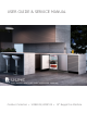
USER GUIDE & SERVICE MANUAL Outdoor Collection ● UONB115/UONP115 ● 15” Nugget Ice Machine
USER GUIDE & SERVICE MANUAL u-line.
USER GUIDE u-line.com WELCOME TO U-LINE Congratulations on your U-Line purchase. Your product comes from a company with over five decades of premium modular ice making, refrigeration, and wine preservation experience. U-Line creates products focused on functionality, style, and inspired innovations — paying close attention to even the smallest details. Applications include residential, outdoor, ADA height compliant, marine, and commercial.
USER GUIDE u-line.com Safety and Warning ! DANGER NOTICE This unit contains R600a (Isobutane) which is a Please read all instructions before installing, flammable hydrocarbon. It is safe for regular operating, or servicing the appliance. use. Do not use sharp objects to expedite Use this appliance for its intended purpose only and follow these general precautions with those listed throughout this guide: defrosting.
USER GUIDE u-line.com Disposal and Recycling ! DANGER RISK OF CHILD ENTRAPMENT. Before you throw away your old refrigerator or freezer, take off the doors and leave shelves in place so children may not easily climb inside. If the unit is being removed from service for disposal, check and obey all federal, state, and local regulations regarding the disposal and recycling of refrigeration appliances, and follow these steps completely: 1. Remove all consumable contents from the unit. 2.
USER GUIDE u-line.com Environmental Requirements This unit is designed to operate between 50°F (10°C) and 100°F (38°C). Higher ambient temperatures may reduce the unit’s ability to reach low temperatures and/or reduce ice production on applicable models. For best performance, keep the unit out of direct sunlight and away from heat generating equipment. In climates where high humidity and dew points are present, condensation may appear on outside surfaces. This is considered normal.
USER GUIDE u-line.com Electrical ! WARNING SHOCK HAZARD — Electrical Grounding Required. Never attempt to repair or perform maintenance on the unit until the electricity has been disconnected. Never remove the round grounding prong from the plug and never use a two-prong grounding adapter. Altering, cutting or removing power cord, removing power plug, or direct wiring can cause serious injury, fire, loss of property and/or life, and will void the warranty.
USER GUIDE u-line.com Cutout & Product Dimensions 14 15⁄16” (379 mm) PREPARE SITE Your U-Line product has been designed for either freestanding or built-in installation. When built-in, your unit does not require additional air space for top, sides, or rear. However, the front grille must NOT be obstructed, FRONT and clearance is required for an electrical connection in 28” (711 mm) 34 1⁄8” to 35 1⁄8” (867 mm to 892 mm) the rear.
USER GUIDE Side-by-Side Installation u-line.com 3. Place bracket over holes and attach to unit with two screws removed in step 2 using a T-25 Torx driver. Two units may be installed side-by-side. Cutout width for a side-by-side installation is the cutout Tighten screws fully. 4. Gently push units into position. Be careful not to dimension of a single unit times two. No trim kit is required. However, 1/4" (6 mm) of space entangle the electrical cord or water line, if applicable. 5.
USER GUIDE u-line.com Water Hookup • The water pressure should be between 20 and 120 psi (138 and 827 kPa). PREPARE PLUMBING The water valve uses a standard 1/4” (6.35 mm) • supply line. compression fitting. U-Line recommends using accessory water hook up kit – part # 80-54674-00. The kit includes a 10’ (3 m) braided flexible water supply line and a brass The water line MUST have a shut-off valve in the • The water line should be looped into 2 coils.
USER GUIDE 3. u-line.com Thread water line through back panel hole (with bushing). 4. Locate water valve inlet and connect to valve. 3 4 5. Turn on water supply and check for leaks. 6. Reinstall back panel.
USER GUIDE Drain u-line.com GRAVITY DRAIN Model numbers including “CL” or “NB” do not include a factory installed drain pump. Normal Proper Drain Model numbers including “CP” or “NP” include a factory installed drain pump. With Trap Poor Drainage, Water Will Back Up DRAIN CONNECTION ! CAUTION With Trap and Vent Proper Drain If your U-Line unit did not come with a factory installed drain pump you must use a gravity style drain connection.
USER GUIDE u-line.com FACTORY INSTALLED DRAIN PUMP If your drain line will run up to a stand pipe, disposal Y-Branch Tailpiece P60 Pump Required or spigot assembly, or does not otherwise meet the Air Gap (Optional Hook-Up) requirements for a gravity drain, you may have ordered a pre-installed U-Line P60 drain pump. Waste If you need to install a P60 drain pump into your unit, see Shut-Off Valve DRAIN PUMP section in the User Manual.
USER GUIDE u-line.com Anti-Tip Bracket 1. Slide unit out so screws on top of unit are easily accessible. 2. Remove the two screws from the opposite side of the hinge assembly using a T-25 Torx driver (see below). 3. Place bracket over holes and attach to unit with two screws removed in step 2 using a T-25 Torx driver. Tighten screws fully. 4. Gently push unit into position. Be careful not to entangle the electrical cord or water line, if applicable. 5.
USER GUIDE u-line.com General Installation INSTALLATION LEVELING INFORMATION 1. Use a level to 1. Plug in the power/electrical cord. 2. Gently push the unit into position. Be careful not to entangle the cord or water and drain lines, if confirm the unit is applicable. level. Level should 3. be placed along top Re-check the leveling, from front to back and side to edge and side edge side. Make any necessary adjustments. The unit’s top as shown.
USER GUIDE u-line.com Grille Installation REMOVING AND INSTALLING GRILLE ! WARNING Disconnect electric power to the unit before removing the grille. When using the unit, the grille must be installed. ! WARNING DO NOT touch the condenser fins. The condenser fins are SHARP and can be easily damaged. Removing the grille 1. Disconnect power to the unit. 2. Loosen the two screws (1). 3. Remove grille (2) from unit. Installing the grille 1.
USER GUIDE u-line.com Door Swing Wall 2-1/8" Min. (54 mm) 90° Door Swing Units have a zero clearance for the door to open 90°, when installed adjacent to cabinets. Stainless Steel models require 2-1/8" (54 mm) door clearance to accommodate the handle if installed next to a wall.
USER GUIDE u-line.com Door Adjustments REVERSING THE DOOR Location of the unit may make it desirable to mount the HINGE COVER door on the opposite side of the cabinet. Hinge cover included with the literature bag is optional. The hinge hardware will be removed and reinstalled on the opposite side of the cabinet. TO REVERSE THE DOOR To install hinge cover: 1. Press hinge cover squarely over hinge. Hinge Cover Remove grille: Remove the grille (see GRILLE INSTALLATION section of this guide).
USER GUIDE 3. u-line.com Remove door by tilting forward and lifting door off Prepare door for reinstallation: bottom hinge. Retain shoulder washers; they will be reused. USER GUIDE 4. Insert arrow clips into holes. 1. magnet assembly. 2. 4. Remove door by tilting forward and lifting door off bottom hinge. Retain shoulder washers; they will be reused. 5. Remove three screws from hinge holes on the opposite side. Reinstall into holes where the hinge was 3.
USER GUIDE u-line.com Control Operation CONTROL FUNCTION GUIDE FUNCTION COMMAND NOTES ON/OFF Press Unit will immediately turn On or OFF Adjust ice density See “Ice” section Enable Sabbath Mode Press and release The oF / oC symbol will flash briefly after 5 seconds.
USER GUIDE u-line.com Ice The Nugget Ice Machine produces cylindrical bits of compressed ice approximately 3/4” x 1/2”. Ice is produced until the machine senses the bin is full. As ice slowly melts in the bin, the level of ice drops and ice production resumes. This ensures a constant supply of fresh ice is always available. The factory default ice setting is 0, which produces a firm and compact ice nugget.
USER GUIDE u-line.com Airflow and Product Loading NOTICE The unit requires proper airflow to perform at its highest efficiency. Do not block the front grille at any time, or the unit will not perform as expected. Do not install the unit behind a door.
USER GUIDE Cleaning u-line.com Integrated Models To clean integrated panels, use household cleaner per the EXTERIOR CLEANING cabinet manufacturer’s recommendations. Vinyl Clad (Black or White) Models Clean surfaces with a mild detergent and warm water INTERIOR CLEANING solution. Do not use solvent-based or abrasive cleaners. Disconnect power to the unit. Use a soft sponge and rinse with clean water.
USER GUIDE u-line.com Under normal conditions cleaning should be done when the display shows Cl CL. You may initiate a cleaning cycle at any time by pressing and holding the clean button for 10 seconds. 0 1 will appear in the display indicating the start of the cleaning 1. Press and Hold a. process. for 10 seconds 0 1 will appear in the display b. Remove access shield Failure to clean may reduce the quality and quantity of ice c. Remove all ice in bin produced.
USER GUIDE 6. When u-line.com 05 appears in the display, 3 soft tones will sound, indicating the cleaning phase is complete a. Remove and discard water filter if applicable by rotating 1⁄4 turn counterclockwise. b. Use the remaining cleaning solution to wipe the manifold and surrounding area. Rinse with clean potable water. Manifold (Filter Models Only) c. Using the hose and funnel, slowly pour 1.5 quarts (48 oz.) of clean potable water into the ice dispenser tube.
USER GUIDE u-line.com Cleaning Condenser INTERVAL - EVERY SIX MONTHS To maintain operational efficiency, keep the front grille free of dust and lint, and clean the condenser when necessary. Depending on environmental conditions, more or less frequent cleaning may be necessary. ! WARNING Disconnect electric power to the unit before cleaning the condenser. NOTICE DO NOT use any type of cleaner on the condenser unit. Condenser may be cleaned using a vacuum, soft brush, or compressed air. 1.
USER GUIDE u-line.com Extended Non-Use VACATION/HOLIDAY, PROLONGED SHUTDOWN For questions regarding winterization, please call U-Line at 414.354.0300. The following steps are recommended for periods of extended non-use: 1. ! CAUTION Remove all consumable content from the unit. Damage caused by freezing temperatures is not 2. Disconnect the power cord from its outlet/socket and leave it disconnected until the unit is returned to service. 3. Turn off the water supply. 4.
USER GUIDE u-line.com Troubleshooting • Evaporator: Refrigerant flowing through an evaporator may sound like boiling liquid. BEFORE CALLING FOR SERVICE • Condenser Fan: Air moving through a condenser may be heard. • Automatic Defrost Drain Pan: Water may be heard dripping or running into the drain pan when the unit is in the defrost cycle. If you think your U-Line product is malfunctioning, read the CONTROL OPERATION section to clearly understand the function of the control.
USER GUIDE CHECKING PRODUCT TEMPERATURE u-line.com Causes which affect the internal temperatures of the cabinet include: • Temperature setting. • Ambient temperature where installed. • Installation in direct sunlight or near a heat source. • The number of door openings and the time the door is open. To check the actual product temperature in the unit: • The time the internal light is illuminated. (This mainly affects product on the top rack or shelf.) 1.
W 11 22 12 IFI An te n 1 g 6 1 VC C 1 FUSE Open Yellow Blue Purple Black/Yellow Open Open Black N.C. White 4 lay 1 10 5 Pump P Condenser Fan M Auger Resevoir Valve Dump Valve 120 V Wire Diagram Pump Door switch Water shutoff Low water sensor Bin temp White light na 1 bu De Programming Wire Diagram sp Di 42379_B USER GUIDE u-line.
USER GUIDE u-line.com Product Liability Field service technicians are authorized to make an initial assessment in the event of reported damages. If there are any questions about the process involved, the technician should call U-Line for further explanation. While inspecting for defects or installation issues, photos should be taken to document any damages or issues found.
USER GUIDE Warranty Claims The following information defines the parameters for filing a warranty claim: Units must be registered prior to warranty submittal. Customers may register at www.U-Line.com. A proof of purchase is required. We also accept the following information to update warranty: • Valid serial number needed • Valid model number needed • Claims must be submitted online at www.U-LineService.com • u-line.
USER GUIDE u-line.
USER GUIDE u-line.
USER GUIDE u-line.com Ordering Replacement Parts Parts may be ordered online at www.U-Line.com See our contact information below: www.U-LineService.com (with service login) Phone Number: +1.800.779.2547 NOTICE Use only genuine U-Line replacement parts. The use of non-U-Line parts can reduce speed of ice production, cause water to overflow from ice maker mold, damage the unit, and void the warranty. Warranty parts will be shipped at no charge after U-Line confirms warranty status.
USER USER GUIDE GUIDE u-line.com u-line.com SAFETY • INSTALLATION & INTEGRATION • OPERATING INSTRUCTIONS • MAINTENANCE • SERVICE R-600A Specifications Gloves and Eye Protection must be used. For R-600a refrigerant service tips and more videos, go to: www.u-line.com/videos. ! WARNING Flammability warnings for a pure-iso-butane refrigerant. R-600a is considered non-toxic, but is flammable when mixed with air. Keep a dry powder type fire extinguisher in the work area.
USER USER GUIDE GUIDE u-line.com u-line.com SAFETY • INSTALLATION & INTEGRATION • OPERATING INSTRUCTIONS • MAINTENANCE • SERVICE ! WARNING Only skilled and well trained service technicians permitted to service R-600a equipped products. R-600A SPECIFICATIONS/LABELING R-600a equipped products are labeled (both the unit and the compressor). R-600a is colorless and odorless. All tools and equipment must be approved for use with R-600a refrigerant.
USER GUIDE GUIDE USER u-line.com u-line.com SAFETY • INSTALLATION & INTEGRATION • OPERATING INSTRUCTIONS • MAINTENANCE • SERVICE Evacuate/reclaim via the piecing pliers to ensure the When re-brazing, the system must be purged with dry system is empty of R-600a before any system work is nitrogen and at least one access point open to the performed. atmosphere. When re-brazing, proper ventilation is required along with constant monitoring for the presence of R600a refrigerant.
USER GUIDE GUIDE USER u-line.com u-line.com SAFETY • INSTALLATION & INTEGRATION • OPERATING INSTRUCTIONS • MAINTENANCE • SERVICE The low side of the refrigeration system (evaporator, Proper ventilation during service is required. compressor and suction line) must be leak tested with the compressor off (equalized pressure). Never apply a torch to a charged R-600a refrigeration system. RECHARGING No air is ever to be allowed inside the refrigeration system (R-600a refrigerant or dry nitrogen only).
USER GUIDE u-line.
USER GUIDE u-line.com Compressor Specifications FMXA9C REFRIGERANT R600A VOLTAGE 230 VAC FREQUENCY 43-134 Hz Electrocution can cause death or serious injury. START WINDING 20 Ohm at 77o F Burns from hot or cold surfaces can cause serious RUN WINDING 20 Ohm at 77o F injury. Take precautions when servicing this unit. RUN TO START 20 Ohm at 77o F LRA 1.7 A FLA 1.7 A STARTING DEVICE Inverter CF02C05 OVERLOAD Inverter CF02C05 ! DANGER Disconnect the power source.
USER GUIDE Troubleshooting - Extended u-line.com • Evaporator: Refrigerant flowing through an evaporator may sound like boiling liquid. SPECIFIC ERRORS AND ISSUES The advanced diagnostic capabilities of the electronic • be heard. controls utilized on the 1, 3, and 5 Class units allow for easy and thorough troubleshooting. • in the defrost cycle. the CONTROL OPERATION section of the manual, along a service mode menu and service menu selection explanations.
USER GUIDE u-line.com MAIN CONTROL Check Voltage At Wall Outlet The main control board is very robust and is rarely the cause of system issues. It is important to fully diagnose No Voltage Alert Customer Of Power Failure No Voltage Replace Power Cord No Continuity Replace Fuse Voltage the board for any suspected failures before attempting to remove the board for replacement or service.
USER GUIDE Relay & DC Outputs One of the primary functions of the main control is to operate the multiple relay and DC outputs during each cycle. Verify proper operation of these relays using the following procedure. 1. Enter “Relay Toggle” through the service menu. u-line.com PLUNGER SWITCH A plunger switch is used to monitor door state. When the door is closed it comes into contact with the plunger which closes a circuit which turns the light and display off.
USER GUIDE u-line.com b. APPENDIX any leakage addressed with a seal kit. (U-Line service part # 80-55371-13) E11: Sensor in base near fan detecting water This sensor is designed to detect water escaping the product due to any type of malfunction inside the machine.
USER GUIDE b. u-line.com If unit fills, the float switch is malfunctioning and d. needs to be replaced (part # 80-55538-00). 4. Check compressor operation. • If unit is 3 Class product, enter service mode and operating, diagnose and fix system problem. activate relays 1 and 4 to determine if unit fills with • water. a. • If there is power, check valve resistance to connections to auger. 3.
USER GUIDE u-line.com Control Operation-Service CONTROL FUNCTION GUIDE UI BUTTON LAYOUT 1 1. 2 3 4 5 6 Hidden Button -Access Service Menu -No LED directly above. All LEDs turn on with button 2.
USER GUIDE u-line.com SERVICE MODE GUIDE SERVICE MODE GUIDE 0. Exit 1. Thermistor 1 temperature not including offsets. 2. Thermistor 2 temperature not including offsets. 3. Thermistor 3 temperature not including offsets. 4. Thermistor 4 temperature not including offsets. 5. Thermistor 1 offset. (+/- 10) 6. Thermistor 2 offset. (+/- 10) 7. Thermistor 3 offset. (+/- 10) 8. Thermistor 4 offset. (+/- 10) 9. Thermistor 2 set point 10. Thermistor 3 set point. 11. Thermistor 4 set point. 12.
USER GUIDE u-line.com 15. CLEAR ERROR LOG To clear errors, press and hold (5 seconds) when CLR is flashing. 16. THERMISTOR - 1 DIFFERENTIAL This number should not be adjusted 17. Does not apply to this model 18. Does not apply to this model 19. Does not apply to this model 20.
USER GUIDE u-line.
Comp/Fan Compressor Compressor Clear Ice, 3 Class **BV315-***1A 01 Control Operation-Service 51 Compressor Compressor Compressor **WD524-***1A **RF124-***1A **RI124-***1A 46 48 52 50 Compressor Compressor **BD524-***1A **WD324-***1A 43 Compressor Compressor **WC336-***1A **BD324-***1A 40 Compressor **WC524-***1A 37 38 41 Compressor Compressor **WC324-***1A **WC515-***1A 35 Compressor Compressor **WC315-***1A **WC318-***1A 32 Compressor **KR524-***1A 27 29 33 Compresso
USER GUIDE Thermistor u-line.com Thermistor Resistance Data Thermistors are used for various temperature readings. Thermistors provide reliable temperature readings using a resistance which varies based on surrounding temperatures. If a faulty thermistor is suspected, it may be tested using an accurate ohmmeter. Thermistor connections must be kept clean.
U-Line Corporation (U-Line) Limited Warranty One Year Limited Warranty For one year from the date of original purchase, this warranty covers all parts and labor to repair or replace any part of the product that proves to be defective in materials or workmanship. For products installed and used for normal residential use, material cosmetic defects are included in this warranty, with coverage limited to 60 days from the date of original purchase.