
Operating instructions


pul
se
cons
1s
ts
of a
negative-going
trans1t1on
of
about
5 volts
and
100-ns
duration,
followed
immediatel
y by a
pos
itive
transition
of
about
5
volt
s
and
150-ns
duration.
The
initial
negative-going
trans
ition
will
trigger
the
input
circuits
and
start
the
main
pulse
of a
following
Type 1398-A.
The
positive-going
transition
will
then
re
set
the
in
put
circuits
of
the
second
Ty
pe
1398-A
to
prepare
it
for
the
ne xt
de
l
ayed
pulse.
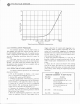
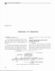
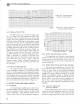
Figure
3-8
shows
con
nec
ti
ons
and
timing
waveforms
of
such
a
sys
tem.
TYPE
12
10-C
UNIT
R-C
OSCI
LLATOR
TYPE 1210-C
TY
PE
1398-A ,
*II
PREPULSE
TY
PE
1398-A,*II
MAIN
PULSE( N
EG)
~~W~6
8
r~L~~
----,1c~------~-------
TYP~
1398-A,
112
____
=F4-.-~
ll.__
__
_
MAIN
PULSE
Figure
3-8 .
Connection
of
two
Type
1398
-
A's
os
a
delay
generator.
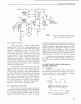
OPERATING
PROCEDURE
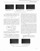
3.13
USE
FOR
COMPLEX
WAVEFORMS.
Since
the
output
circuit
of
the
Type
1398-A
is
essentially
a
current
source
feeding
a
resistive
load,
the
outputs
of
two
or more
pulse
generators
can
be
directly_
paralleled
to
produce
complex
additive
wave-
forms.
The
output
impedance
of
n
pulse
generators
so
paralleled
is
1000/n
ohms
and
the
peak
voltage
is
s
till
60
volts.
A
complex
waveform
and
the
system
to
produce
it
are
shown
in
Figure
3-9.
TYPE
1398-A
PULSE
GENERATOR,'~!'
I
TYPE
1398-All3
OUTPUT
Figure
3-9
.
System
for
producing
the
complex
waveform
shown.
13