
Operating instructions


19
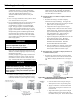
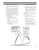
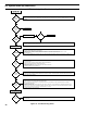
a. Pilotamecurrentinmicroampscanbe
measured using any standard micro-ammeter by
inserting the meter probes into the module holes
labeled FLAME CURRENT as shown in Figure
17B.
b. Flame current must be measured with pilot
valve open/pilot lit but the main valve closed.
c. Disconnect MV lead wire from the module
beforemeasuringamecurrent.Tryingto
measurethepilotamecurrentinserieswiththe
wiring will not yield the accurate reading.
d. The minimum steady pilot ame signal must
be 1 μAmp (microampere) DC (direct current).
e. For reliable operationtheamecurrentshould
be 2 μAmp or greater.
f. To ensure adequate ame current:
i. Turn off boiler power at circuit breaker or
fuse box
ii. Cleantheamerodwithemeryclothif
required
iii. Make sure electrical connections are clean
and tight, and wiring not damaged, repair/
replace as needed
iv. Check for igniter/sensor cracked ceramic
insulator, replace if needed
Figure 17B: Measuring Pilot Flame Current with Micro-ammeter
v. Checkthepilotame.Itmustbeblue,
steadyandenveloptheamesensingrod
3/8” to ½”.
vi. Ifneeded,adjustpilotamebyturningthe
gas valve pilot adjustment screw clockwise
to decrease or counterclockwise to increase
pilotame.Alwaysreinstallpilotadjustment
screw cover and tighten securely upon
completion to assure proper gas valve
operation.
g. Reconnect MV lead wire to the module upon
satisfactorycompletionofpilotamecurrent
measurement.
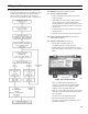
h. Check the pilot burner operation/ignition
sequence during ignition cycle:
i. Restore boiler power at circuit breaker or
fuse box
ii. Set thermostat to call for heat
iii. Watch ignition sequence at burner
iv. If spark does not stop after pilot lights,
replace ignition module
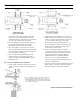
v. If main burners do not light or if main
burners light but system locks out, check the
module ground wire and gas control as
described in Figure 18 “ Honeywell
Electronic Ignition Troubleshooting Guide”
VII. System Start-up (continued)